HD64F2676VFC33 Renesas Electronics America, HD64F2676VFC33 Datasheet - Page 32

HD64F2676VFC33
Manufacturer Part Number
HD64F2676VFC33
Description
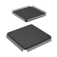
IC H8S MCU FLASH 256K 144-QFP
Manufacturer
Renesas Electronics America
Series
H8® H8S/2600r
Specifications of HD64F2676VFC33
Core Processor
H8S/2600
Core Size
16-Bit
Speed
33MHz
Connectivity
IrDA, SCI
Peripherals
DMA, POR, PWM, WDT
Number Of I /o
103
Program Memory Size
256KB (256K x 8)
Program Memory Type
FLASH
Ram Size
8K x 8
Voltage - Supply (vcc/vdd)
3 V ~ 3.6 V
Data Converters
A/D 12x10b; D/A 4x8b
Oscillator Type
Internal
Operating Temperature
-20°C ~ 75°C
Package / Case
144-QFP
Lead Free Status / RoHS Status
Contains lead / RoHS non-compliant
Eeprom Size
-
Available stocks
Company
Part Number
Manufacturer
Quantity
Price
Company:
Part Number:
HD64F2676VFC33
Manufacturer:
RENESAS
Quantity:
5 530
Company:
Part Number:
HD64F2676VFC33
Manufacturer:
Renesas Electronics America
Quantity:
10 000
Company:
Part Number:
HD64F2676VFC33V
Manufacturer:
RENESAS
Quantity:
5 530
Company:
Part Number:
HD64F2676VFC33V
Manufacturer:
ROHM
Quantity:
750 000
Part Number:
HD64F2676VFC33V
Manufacturer:
RENESAS/瑞萨
Quantity:
20 000
- Current page: 32 of 981
- Download datasheet (6Mb)
Section 1 Overview
Figure 1.1
Figure 1.2
Figure 1.3
Figure 1.4
Section 2 CPU
Figure 2.1
Figure 2.2
Figure 2.3
Figure 2.4
Figure 2.5
Figure 2.6
Figure 2.7
Figure 2.8
Figure 2.9
Figure 2.9
Figure 2.10
Figure 2.11
Figure 2.12
Figure 2.13
Section 3 MCU Operating Modes
Figure 3.1
Figure 3.1
Figure 3.1
Figure 3.1
Figure 3.2
Figure 3.2
Figure 3.3
Figure 3.3
Figure 3.4
Figure 3.5
Section 4 Exception Handling
Figure 4.1
Figure 4.2
Figure 4.3
Rev. 3.00 Mar 17, 2006 page xxx of l
H8S/2678 Group Internal Block Diagram ...........................................................
H8S/2678R Group Internal Block Diagram.........................................................
H8S/2678 Group Pin Arrangement......................................................................
H8S/2678R Group Pin Arrangement ...................................................................
Exception Vector Table (Normal Mode) ............................................................. 25
Stack Structure in Normal Mode ......................................................................... 25
Exception Vector Table (Advanced Mode) ......................................................... 26
Stack Structure in Advanced Mode ..................................................................... 27
Memory Map ....................................................................................................... 28
CPU Registers...................................................................................................... 29
Usage of General Registers.................................................................................. 30
Stack .................................................................................................................... 31
General Register Data Formats (1) ...................................................................... 34
General Register Data Formats (2) ...................................................................... 35
Memory Data Formats ......................................................................................... 36
Instruction Formats (Examples)........................................................................... 48
Branch Address Specification in Memory Indirect Mode.................................... 52
State Transitions................................................................................................... 56
H8S/2676 Memory Map (1)................................................................................. 65
H8S/2676 Memory Map (2)................................................................................. 66
H8S/2676 Memory Map (3)................................................................................. 67
H8S/2676 Memory Map (4)................................................................................. 68
H8S/2675 Memory Map (1)................................................................................. 69
H8S/2675 Memory Map (2)................................................................................. 70
H8S/2673 Memory Map (1)................................................................................. 71
H8S/2673 Memory Map (2)................................................................................. 72
H8S/2670 Memory Map ...................................................................................... 73
H8S/2674R Memory Map.................................................................................... 74
Reset Sequence (Advanced Mode with On-Chip ROM Enabled) ....................... 78
Reset Sequence (Advanced Mode with On-Chip ROM Disabled) ...................... 79
Stack Status after Exception Handling................................................................. 82
Figures
3
4
5
6
Related parts for HD64F2676VFC33
Image
Part Number
Description
Manufacturer
Datasheet
Request
R

Part Number:
Description:
KIT STARTER FOR M16C/29
Manufacturer:
Renesas Electronics America
Datasheet:

Part Number:
Description:
KIT STARTER FOR R8C/2D
Manufacturer:
Renesas Electronics America
Datasheet:

Part Number:
Description:
R0K33062P STARTER KIT
Manufacturer:
Renesas Electronics America
Datasheet:

Part Number:
Description:
KIT STARTER FOR R8C/23 E8A
Manufacturer:
Renesas Electronics America
Datasheet:

Part Number:
Description:
KIT STARTER FOR R8C/25
Manufacturer:
Renesas Electronics America
Datasheet:

Part Number:
Description:
KIT STARTER H8S2456 SHARPE DSPLY
Manufacturer:
Renesas Electronics America
Datasheet:

Part Number:
Description:
KIT STARTER FOR R8C38C
Manufacturer:
Renesas Electronics America
Datasheet:

Part Number:
Description:
KIT STARTER FOR R8C35C
Manufacturer:
Renesas Electronics America
Datasheet:

Part Number:
Description:
KIT STARTER FOR R8CL3AC+LCD APPS
Manufacturer:
Renesas Electronics America
Datasheet:

Part Number:
Description:
KIT STARTER FOR RX610
Manufacturer:
Renesas Electronics America
Datasheet:

Part Number:
Description:
KIT STARTER FOR R32C/118
Manufacturer:
Renesas Electronics America
Datasheet:

Part Number:
Description:
KIT DEV RSK-R8C/26-29
Manufacturer:
Renesas Electronics America
Datasheet:

Part Number:
Description:
KIT STARTER FOR SH7124
Manufacturer:
Renesas Electronics America
Datasheet:

Part Number:
Description:
KIT STARTER FOR H8SX/1622
Manufacturer:
Renesas Electronics America
Datasheet:

Part Number:
Description:
KIT DEV FOR SH7203
Manufacturer:
Renesas Electronics America
Datasheet:


