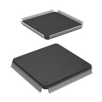
HD64F2676VFC33 Renesas Electronics America, HD64F2676VFC33 Datasheet - Page 954

HD64F2676VFC33
Manufacturer Part Number
HD64F2676VFC33
Description
IC H8S MCU FLASH 256K 144-QFP
Manufacturer
Renesas Electronics America
Series
H8® H8S/2600r
Specifications of HD64F2676VFC33
Core Processor
H8S/2600
Core Size
16-Bit
Speed
33MHz
Connectivity
IrDA, SCI
Peripherals
DMA, POR, PWM, WDT
Number Of I /o
103
Program Memory Size
256KB (256K x 8)
Program Memory Type
FLASH
Ram Size
8K x 8
Voltage - Supply (vcc/vdd)
3 V ~ 3.6 V
Data Converters
A/D 12x10b; D/A 4x8b
Oscillator Type
Internal
Operating Temperature
-20°C ~ 75°C
Package / Case
144-QFP
Lead Free Status / RoHS Status
Contains lead / RoHS non-compliant
Eeprom Size
-
Available stocks
Company
Part Number
Manufacturer
Quantity
Price
Company:
Part Number:
HD64F2676VFC33
Manufacturer:
RENESAS
Quantity:
5 530
Company:
Part Number:
HD64F2676VFC33
Manufacturer:
Renesas Electronics America
Quantity:
10 000
Company:
Part Number:
HD64F2676VFC33V
Manufacturer:
RENESAS
Quantity:
5 530
Company:
Part Number:
HD64F2676VFC33V
Manufacturer:
ROHM
Quantity:
750 000
Part Number:
HD64F2676VFC33V
Manufacturer:
RENESAS/瑞萨
Quantity:
20 000
- Current page: 954 of 981
- Download datasheet (6Mb)
Section 24 Electrical Characteristics
Timing of On-Chip Peripheral Modules
Table 24.10 Timing of On-Chip Peripheral Modules
Conditions: V
Rev. 3.00 Mar 17, 2006 page 902 of 926
REJ09B0283-0300
Item
I/O ports
PPG
TPU
8-bit timer
WDT
SCI
A/D
converter
Output data delay time
Input data setup time
Input data hold time
Pulse output delay time
Timer output delay time
Timer input setup time
Timer clock input setup time
Timer clock
pulse width
Timer output delay time
Timer reset input setup time
Timer clock input setup time
Timer clock
pulse width
Overflow output delay time
Input clock
cycle
Input clock pulse width
Input clock rise time
Input clock fall time
Transmit data delay time
Receive data setup time
(synchronous)
Receive data hold time
(synchronous)
Trigger input setup time
T
a
CC
= 8 MHz to 33 MHz, T
= –40°C to +85°C (wide-range specifications)
= 3.0 V to 3.6 V, AV
Single-edge
specification
Both-edge
specification
Single-edge
specification
Both-edge
specification
Asynchronous
Synchronous
a
CC
= –20°C to +75°C (regular specifications),
= 3.0 V to 3.6 V, V
Symbol
t
t
t
t
t
t
t
t
t
t
t
t
t
t
t
t
t
t
t
t
t
t
t
PWD
PRS
PRH
POD
TOCD
TICS
TCKS
TCKWH
TCKWL
TMOD
TMRS
TMCS
TMCWH
TMCWL
WOVD
Scyc
SCKW
SCKr
SCKf
TXD
RXS
RXH
TRGS
—
25
25
—
—
25
25
1.5
2.5
—
25
25
1.5
2.5
—
4
6
0.4
—
—
—
40
40
30
Min
ref
= 3.0 V to AV
Max
40
—
—
40
40
—
—
—
—
40
—
—
—
—
40
—
—
0.6
1.5
1.5
40
—
—
—
Unit
ns
ns
ns
ns
ns
ns
ns
t
t
ns
ns
ns
t
t
ns
t
t
t
ns
ns
ns
ns
cyc
cyc
cyc
cyc
cyc
Scyc
cyc
CC
, V
Test Conditions
Figure 24.34
Figure 24.35
Figure 24.36
Figure 24.37
Figure 24.38
Figure 24.40
Figure 24.39
Figure 24.41
Figure 24.42
Figure 24.43
Figure 24.44
SS
= AV
SS
= 0 V,
Related parts for HD64F2676VFC33
Image
Part Number
Description
Manufacturer
Datasheet
Request
R

Part Number:
Description:
KIT STARTER FOR M16C/29
Manufacturer:
Renesas Electronics America
Datasheet:

Part Number:
Description:
KIT STARTER FOR R8C/2D
Manufacturer:
Renesas Electronics America
Datasheet:

Part Number:
Description:
R0K33062P STARTER KIT
Manufacturer:
Renesas Electronics America
Datasheet:

Part Number:
Description:
KIT STARTER FOR R8C/23 E8A
Manufacturer:
Renesas Electronics America
Datasheet:

Part Number:
Description:
KIT STARTER FOR R8C/25
Manufacturer:
Renesas Electronics America
Datasheet:

Part Number:
Description:
KIT STARTER H8S2456 SHARPE DSPLY
Manufacturer:
Renesas Electronics America
Datasheet:

Part Number:
Description:
KIT STARTER FOR R8C38C
Manufacturer:
Renesas Electronics America
Datasheet:

Part Number:
Description:
KIT STARTER FOR R8C35C
Manufacturer:
Renesas Electronics America
Datasheet:

Part Number:
Description:
KIT STARTER FOR R8CL3AC+LCD APPS
Manufacturer:
Renesas Electronics America
Datasheet:

Part Number:
Description:
KIT STARTER FOR RX610
Manufacturer:
Renesas Electronics America
Datasheet:

Part Number:
Description:
KIT STARTER FOR R32C/118
Manufacturer:
Renesas Electronics America
Datasheet:

Part Number:
Description:
KIT DEV RSK-R8C/26-29
Manufacturer:
Renesas Electronics America
Datasheet:

Part Number:
Description:
KIT STARTER FOR SH7124
Manufacturer:
Renesas Electronics America
Datasheet:

Part Number:
Description:
KIT STARTER FOR H8SX/1622
Manufacturer:
Renesas Electronics America
Datasheet:

Part Number:
Description:
KIT DEV FOR SH7203
Manufacturer:
Renesas Electronics America
Datasheet:


