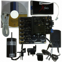
Z8FMC160100KITG Zilog, Z8FMC160100KITG Datasheet - Page 132

Z8FMC160100KITG
Manufacturer Part Number
Z8FMC160100KITG
Description
KIT DEV FOR Z8 ENCORE Z8FMC16100
Manufacturer
Zilog
Series
Z8 Encore! MC™r
Datasheets
1.Z8FMC160100KIT.pdf
(7 pages)
2.Z8FMC160100KIT.pdf
(383 pages)
3.Z8FMC160100KITG.pdf
(2 pages)
4.Z8FMC160100KITG.pdf
(15 pages)
Specifications of Z8FMC160100KITG
Main Purpose
Power Management, Motor Control
Embedded
Yes, MCU, 8-Bit
Utilized Ic / Part
Z8FMC16100
Primary Attributes
3-Ph DC Motors
Secondary Attributes
Graphical User Interface
For Use With
269-4664 - KIT ACC OPTO-ISO USB SMART CABLE269-4661 - KIT ACC ETHERNET SMART CABLE269-4539 - KIT ACCESSORY USB SMART CABLE
Lead Free Status / RoHS Status
Lead free / RoHS Compliant
Other names
269-4660
- Z8FMC160100KIT PDF datasheet
- Z8FMC160100KIT PDF datasheet #2
- Z8FMC160100KITG PDF datasheet #3
- Z8FMC160100KITG PDF datasheet #4
- Current page: 132 of 383
- Download datasheet (5Mb)
PS024613-0910
software. In the LIN Slave mode, the
moves through the Wait For Break, AutoBaud, and Active states.
The Noise Filter may also need to be enabled and configured when interfacing to a LIN
bus.
LIN MASTER Mode Operation
LIN MASTER mode is selected by setting
=
LinState
The Break is the first part of the message frame transmitted by the master, consisting of at
least 13 bit periods of logical zero on the LIN bus. During initialization of the LIN master,
the duration (in bit times) of the Break is written to the
Control register. The transmission of the Break is performed by setting the
Control 0 register. The LIN-UART starts the Break once the
character transmission currently underway has completed. The
hardware once the break is completed.
The Synch character is transmitted by writing a
must = 1 before writing). The Synch character is not transmitted by the hardware until
after the Break is complete.
The Identifier character is transmitted by writing the appropriate value to the Transmit
Data register (
If the master is sending the response portion of the message, these data and checksum
characters are written to the Transmit Data register when the
transmit data register is written after
inserts one or two stop bits between each character as determined by the
Control0 register. Additional idle time occurs between characters if
next character is written.
If the selected slave is sending the response portion of the frame to the master, each receive
byte is signalled by the receive data interrupt (
If the selected slave is sending the response to a different slave, the master can ignore the
response characters by deasserting the
slot has completed.
LIN Sleep Mode
While the LIN bus is in the sleep state, the CPU can be in either low power STOP mode, in
HALT mode, or in normal operational state. Any device on the LIN bus may issue a Wake-
up message if it requires the master to initiate a LIN message frame. Following the Wake-
up message, the master wakes up and initiates a new message. A Wake-up message is
accomplished by pulling the bus low for at least 250 µs but less than 5 ms. Transmitting a
00h
11B.
character is one way to transmit the wake-up message.
If the LIN bus protocol indicates the bus is required go into the LIN sleep state, the
[1:0] bits must be set =
TDRE
must = 1 before writing).
00B
LinState
TDRE
REN
by software.
LMST
bit in the Control0 register until the frame time
asserts, but before
RDA
= 1,
55H
field is updated by hardware as the Slave
bit is set in the Status0 register).
Z8FMC16100 Series Flash MCU
LSLV
to the Transmit Data register (
TxBreakLength
= 0,
TXE
ABEN
Product Specification
SBRK
SBRK
TDRE
TXE
asserts, the hardware
= 0,
bit is deasserted by
bit is set and any
bit asserts. If the
asserts before the
LIN Protocol Mode
LinState
field of the LIN
Stop
SBRK
bit in the
bit in the
TDRE
[1:0]
120
Related parts for Z8FMC160100KITG
Image
Part Number
Description
Manufacturer
Datasheet
Request
R

Part Number:
Description:
Communication Controllers, ZILOG INTELLIGENT PERIPHERAL CONTROLLER (ZIP)
Manufacturer:
Zilog, Inc.
Datasheet:

Part Number:
Description:
KIT DEV FOR Z8 ENCORE 16K TO 64K
Manufacturer:
Zilog
Datasheet:

Part Number:
Description:
KIT DEV Z8 ENCORE XP 28-PIN
Manufacturer:
Zilog
Datasheet:

Part Number:
Description:
DEV KIT FOR Z8 ENCORE 8K/4K
Manufacturer:
Zilog
Datasheet:

Part Number:
Description:
KIT DEV Z8 ENCORE XP 28-PIN
Manufacturer:
Zilog
Datasheet:

Part Number:
Description:
DEV KIT FOR Z8 ENCORE 4K TO 8K
Manufacturer:
Zilog
Datasheet:

Part Number:
Description:
CMOS Z8 microcontroller. ROM 16 Kbytes, RAM 256 bytes, speed 16 MHz, 32 lines I/O, 3.0V to 5.5V
Manufacturer:
Zilog, Inc.
Datasheet:

Part Number:
Description:
Low-cost microcontroller. 512 bytes ROM, 61 bytes RAM, 8 MHz
Manufacturer:
Zilog, Inc.
Datasheet:

Part Number:
Description:
Z8 4K OTP Microcontroller
Manufacturer:
Zilog, Inc.
Datasheet:

Part Number:
Description:
CMOS SUPER8 ROMLESS MCU
Manufacturer:
Zilog, Inc.
Datasheet:

Part Number:
Description:
SL1866 CMOSZ8 OTP Microcontroller
Manufacturer:
Zilog, Inc.
Datasheet:

Part Number:
Description:
SL1866 CMOSZ8 OTP Microcontroller
Manufacturer:
Zilog, Inc.
Datasheet:

Part Number:
Description:
OTP (KB) = 1, RAM = 125, Speed = 12, I/O = 14, 8-bit Timers = 2, Comm Interfaces Other Features = Por, LV Protect, Voltage = 4.5-5.5V
Manufacturer:
Zilog, Inc.
Datasheet:

Part Number:
Description:
Manufacturer:
Zilog, Inc.
Datasheet:


