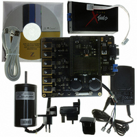
Z8FMC160100KITG Zilog, Z8FMC160100KITG Datasheet - Page 145

Z8FMC160100KITG
Manufacturer Part Number
Z8FMC160100KITG
Description
KIT DEV FOR Z8 ENCORE Z8FMC16100
Manufacturer
Zilog
Series
Z8 Encore! MC™r
Datasheets
1.Z8FMC160100KIT.pdf
(7 pages)
2.Z8FMC160100KIT.pdf
(383 pages)
3.Z8FMC160100KITG.pdf
(2 pages)
4.Z8FMC160100KITG.pdf
(15 pages)
Specifications of Z8FMC160100KITG
Main Purpose
Power Management, Motor Control
Embedded
Yes, MCU, 8-Bit
Utilized Ic / Part
Z8FMC16100
Primary Attributes
3-Ph DC Motors
Secondary Attributes
Graphical User Interface
For Use With
269-4664 - KIT ACC OPTO-ISO USB SMART CABLE269-4661 - KIT ACC ETHERNET SMART CABLE269-4539 - KIT ACCESSORY USB SMART CABLE
Lead Free Status / RoHS Status
Lead free / RoHS Compliant
Other names
269-4660
- Z8FMC160100KIT PDF datasheet
- Z8FMC160100KIT PDF datasheet #2
- Z8FMC160100KITG PDF datasheet #3
- Z8FMC160100KITG PDF datasheet #4
- Current page: 145 of 383
- Download datasheet (5Mb)
Table 71. LIN-UART Control 0 Register (U0CTL0)
PS024613-0910
BITS
FIELD
RESET
R/W
ADDR
LIN-UART Control 0 Register
TEN
R/W
7
0
The LIN-UART Control 0 register
UART’s transmit and receive operations. A more detailed discussion of each bit follows
the table.
TEN—Transmit Enable
This bit enables or disables the transmitter. The enable is also controlled by the CTS signal
and the CTSE bit. If the CTS signal is Low and the CTSE bit is 1, the transmitter is enabled.
0 = Transmitter disabled.
1 = Transmitter enabled.
REN—Receive Enable
This bit enables or disables the receiver.
0 = Receiver disabled.
1 = Receiver enabled.
CTSE—CTS Enable
0 = The CTS signal has no effect on the transmitter.
1 = The LIN-UART recognizes the CTS signal as an enable control for the transmitter.
PEN—Parity Enable
This bit enables or disables parity. Even or odd is determined by the PSEL bit.
0 = Parity is disabled. This bit is overridden by the
1 = The transmitter sends data with an additional parity bit and the receiver receives an
additional parity bit.
PSEL—Parity Select
0 = Even parity is transmitted and expected on all received data.
1 = Odd parity is transmitted and expected on all received data.
SBRK—Send Break
This bit pauses or breaks data transmission. Sending a break interrupts any transmission in
progress, so ensure that the transmitter has finished sending data before setting this bit. In
standard UART mode, the duration of the break is determined by how long software
leaves this bit asserted. Also the duration of any required Stop bits following the break
REN
R/W
6
0
CTSE
R/W
5
0
PEN
R/W
4
0
(Table
F42H
71) configures the basic properties of the LIN-
PSEL
R/W
3
0
MPEN
Z8FMC16100 Series Flash MCU
SBRK
bit.
R/W
2
0
LIN-UART Control 0 Register
Product Specification
STOP
R/W
1
0
LBEN
R/W
0
0
133
Related parts for Z8FMC160100KITG
Image
Part Number
Description
Manufacturer
Datasheet
Request
R

Part Number:
Description:
Communication Controllers, ZILOG INTELLIGENT PERIPHERAL CONTROLLER (ZIP)
Manufacturer:
Zilog, Inc.
Datasheet:

Part Number:
Description:
KIT DEV FOR Z8 ENCORE 16K TO 64K
Manufacturer:
Zilog
Datasheet:

Part Number:
Description:
KIT DEV Z8 ENCORE XP 28-PIN
Manufacturer:
Zilog
Datasheet:

Part Number:
Description:
DEV KIT FOR Z8 ENCORE 8K/4K
Manufacturer:
Zilog
Datasheet:

Part Number:
Description:
KIT DEV Z8 ENCORE XP 28-PIN
Manufacturer:
Zilog
Datasheet:

Part Number:
Description:
DEV KIT FOR Z8 ENCORE 4K TO 8K
Manufacturer:
Zilog
Datasheet:

Part Number:
Description:
CMOS Z8 microcontroller. ROM 16 Kbytes, RAM 256 bytes, speed 16 MHz, 32 lines I/O, 3.0V to 5.5V
Manufacturer:
Zilog, Inc.
Datasheet:

Part Number:
Description:
Low-cost microcontroller. 512 bytes ROM, 61 bytes RAM, 8 MHz
Manufacturer:
Zilog, Inc.
Datasheet:

Part Number:
Description:
Z8 4K OTP Microcontroller
Manufacturer:
Zilog, Inc.
Datasheet:

Part Number:
Description:
CMOS SUPER8 ROMLESS MCU
Manufacturer:
Zilog, Inc.
Datasheet:

Part Number:
Description:
SL1866 CMOSZ8 OTP Microcontroller
Manufacturer:
Zilog, Inc.
Datasheet:

Part Number:
Description:
SL1866 CMOSZ8 OTP Microcontroller
Manufacturer:
Zilog, Inc.
Datasheet:

Part Number:
Description:
OTP (KB) = 1, RAM = 125, Speed = 12, I/O = 14, 8-bit Timers = 2, Comm Interfaces Other Features = Por, LV Protect, Voltage = 4.5-5.5V
Manufacturer:
Zilog, Inc.
Datasheet:

Part Number:
Description:
Manufacturer:
Zilog, Inc.
Datasheet:


