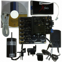
Z8FMC160100KITG Zilog, Z8FMC160100KITG Datasheet - Page 166

Z8FMC160100KITG
Manufacturer Part Number
Z8FMC160100KITG
Description
KIT DEV FOR Z8 ENCORE Z8FMC16100
Manufacturer
Zilog
Series
Z8 Encore! MC™r
Datasheets
1.Z8FMC160100KIT.pdf
(7 pages)
2.Z8FMC160100KIT.pdf
(383 pages)
3.Z8FMC160100KITG.pdf
(2 pages)
4.Z8FMC160100KITG.pdf
(15 pages)
Specifications of Z8FMC160100KITG
Main Purpose
Power Management, Motor Control
Embedded
Yes, MCU, 8-Bit
Utilized Ic / Part
Z8FMC16100
Primary Attributes
3-Ph DC Motors
Secondary Attributes
Graphical User Interface
For Use With
269-4664 - KIT ACC OPTO-ISO USB SMART CABLE269-4661 - KIT ACC ETHERNET SMART CABLE269-4539 - KIT ACCESSORY USB SMART CABLE
Lead Free Status / RoHS Status
Lead free / RoHS Compliant
Other names
269-4660
- Z8FMC160100KIT PDF datasheet
- Z8FMC160100KIT PDF datasheet #2
- Z8FMC160100KITG PDF datasheet #3
- Z8FMC160100KITG PDF datasheet #4
- Current page: 166 of 383
- Download datasheet (5Mb)
PS024613-0910
SPI Interrupts
SPI Baud Rate Generator
The next time SS asserts, the MISO pin outputs SPIDAT[7], regardless of where the
previous transaction suspended. Writing a 1 to
When SPI interrupts are enabled, the SPI generates an interrupt after character
transmission/reception is completed in both MASTER and SLAVE modes. A character
can be defined to be 1–8 bits by the NUMBITS field in the SPI Mode register. In SLAVE
mode, it is not necessary for SS to deassert between characters to generate an interrupt.
The SPI in SLAVE mode can also generate an interrupt if the SS signal deasserts prior to
transfer of all the bits in a character (see description of slave abort error above). Writing a
1 to the IRQ bit in the SPI Status register clears the pending SPI interrupt request. The
IRQ
To start the transfer process, an SPI interrupt can be forced by software to write a 1 to the
STR bit in the SPICTL register.
If the SPI is disabled, an SPI interrupt can be generated by a Baud Rate Generator timeout.
This timer function must be enabled by setting the
Baud Rate Generator timeout does not set the
interrupt bit in the interrupt controller.
In SPI MASTER mode, the Baud Rate Generator creates a lower-frequency serial clock
(SCK) for data transmission synchronization between the master and the external slave.
The input to the Baud Rate Generator is from the system clock. The SPI Baud Rate High
and Low Byte registers combine to form a 16-bit reload value, BRG[15:0], for the SPI
Baud Rate Generator. The SPI baud rate is calculated using the following equation:
Minimum baud rate is obtained by setting BRG[15:0] to
of (2 x 65536 = 131072).
When the SPI is disabled, the Baud Rate Generator can function as a basic 16-bit timer
with an interrupt upon timeout. To configure the Baud Rate Generator as a timer with an
interrupt upon timeout, complete the following procedure:
1. Disable the SPI by clearing the SPIEN bit in the SPI Control register to 0.
2. Load the appropriate 16-bit count value into the SPI Baud Rate High and Low Byte
3. Enable the Baud Rate Generator timer function and the associated interrupt by setting
SPI Baud Rate (bps) =
registers.
the
bit must be cleared to 0 by the interrupt service routine to generate future interrupts.
BIRQ
bit in the SPI Control register to 1.
System Clock Frequency (Hz)
2 x BRG[15:0]
IRQ
ABT
bit in the SPISTAT register, just the SPI
clears this error flag.
BIRQ
Z8FMC16100 Series Flash MCU
0000h
bit in the SPICTL register. This
Product Specification
for a clock divisor value
SPI Interrupts
154
Related parts for Z8FMC160100KITG
Image
Part Number
Description
Manufacturer
Datasheet
Request
R

Part Number:
Description:
Communication Controllers, ZILOG INTELLIGENT PERIPHERAL CONTROLLER (ZIP)
Manufacturer:
Zilog, Inc.
Datasheet:

Part Number:
Description:
KIT DEV FOR Z8 ENCORE 16K TO 64K
Manufacturer:
Zilog
Datasheet:

Part Number:
Description:
KIT DEV Z8 ENCORE XP 28-PIN
Manufacturer:
Zilog
Datasheet:

Part Number:
Description:
DEV KIT FOR Z8 ENCORE 8K/4K
Manufacturer:
Zilog
Datasheet:

Part Number:
Description:
KIT DEV Z8 ENCORE XP 28-PIN
Manufacturer:
Zilog
Datasheet:

Part Number:
Description:
DEV KIT FOR Z8 ENCORE 4K TO 8K
Manufacturer:
Zilog
Datasheet:

Part Number:
Description:
CMOS Z8 microcontroller. ROM 16 Kbytes, RAM 256 bytes, speed 16 MHz, 32 lines I/O, 3.0V to 5.5V
Manufacturer:
Zilog, Inc.
Datasheet:

Part Number:
Description:
Low-cost microcontroller. 512 bytes ROM, 61 bytes RAM, 8 MHz
Manufacturer:
Zilog, Inc.
Datasheet:

Part Number:
Description:
Z8 4K OTP Microcontroller
Manufacturer:
Zilog, Inc.
Datasheet:

Part Number:
Description:
CMOS SUPER8 ROMLESS MCU
Manufacturer:
Zilog, Inc.
Datasheet:

Part Number:
Description:
SL1866 CMOSZ8 OTP Microcontroller
Manufacturer:
Zilog, Inc.
Datasheet:

Part Number:
Description:
SL1866 CMOSZ8 OTP Microcontroller
Manufacturer:
Zilog, Inc.
Datasheet:

Part Number:
Description:
OTP (KB) = 1, RAM = 125, Speed = 12, I/O = 14, 8-bit Timers = 2, Comm Interfaces Other Features = Por, LV Protect, Voltage = 4.5-5.5V
Manufacturer:
Zilog, Inc.
Datasheet:

Part Number:
Description:
Manufacturer:
Zilog, Inc.
Datasheet:


