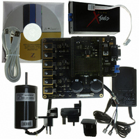
Z8FMC160100KITG Zilog, Z8FMC160100KITG Datasheet - Page 319

Z8FMC160100KITG
Manufacturer Part Number
Z8FMC160100KITG
Description
KIT DEV FOR Z8 ENCORE Z8FMC16100
Manufacturer
Zilog
Series
Z8 Encore! MC™r
Datasheets
1.Z8FMC160100KIT.pdf
(7 pages)
2.Z8FMC160100KIT.pdf
(383 pages)
3.Z8FMC160100KITG.pdf
(2 pages)
4.Z8FMC160100KITG.pdf
(15 pages)
Specifications of Z8FMC160100KITG
Main Purpose
Power Management, Motor Control
Embedded
Yes, MCU, 8-Bit
Utilized Ic / Part
Z8FMC16100
Primary Attributes
3-Ph DC Motors
Secondary Attributes
Graphical User Interface
For Use With
269-4664 - KIT ACC OPTO-ISO USB SMART CABLE269-4661 - KIT ACC ETHERNET SMART CABLE269-4539 - KIT ACCESSORY USB SMART CABLE
Lead Free Status / RoHS Status
Lead free / RoHS Compliant
Other names
269-4660
- Z8FMC160100KIT PDF datasheet
- Z8FMC160100KIT PDF datasheet #2
- Z8FMC160100KITG PDF datasheet #3
- Z8FMC160100KITG PDF datasheet #4
- Current page: 319 of 383
- Download datasheet (5Mb)
PS024613-0910
Bit
Position
[7]
TEN
[6]
TPOL
Value (H) Description
0
1
Timer is enabled.
Timer is disabled.
Timer is enabled.
Timer Input/Output Polarity
This bit is a function of the current operating mode of the timer. It determines the
polarity of the input and/or output signal. When the timer is disabled, the Timer
Output signal is set to the value of this bit.
ONE-SHOT mode–If the timer is enabled the Timer Output signal pulses
(changes state) for one system clock cycle after timer Reload.
CONTINUOUS mode–If the timer is enabled the Timer Output signal is
complemented after timer Reload.
COUNTER mode–If the timer is enabled the Timer Output signal is
complemented after timer reload.
0 = Count occurs on the rising edge of the Timer Input signal.
1 = Count occurs on the falling edge of the Timer Input signal.
PWM SINGLE OUTPUT mode–When enabled, the Timer Output is forced to
TPOL after PWM count match and forced back to TPOL after Reload.
CAPTURE mode–If the timer is enabled the Timer Output signal is
complemented after timer Reload.
0 = Count is captured on the rising edge of the Timer Input signal.
1 = Count is captured on the falling edge of the Timer Input signal.
COMPARE mode–The Timer Output signal is complemented after timer
Reload.
GATED mode–The Timer Output signal is complemented after timer Reload.
0 = Timer counts when the Timer Input signal is High and interrupts are
generated on the falling edge of the Timer Input.
1 = Timer counts when the Timer Input signal is Low and interrupts are
generated on the rising edge of the Timer Input.
CAPTURE/COMPARE mode–If the timer is enabled, the Timer Output signal is
complemented after timer Reload
0 = Counting starts on the first rising edge of the Timer Input signal. The current
count is captured on subsequent rising edges of the Timer Input signal.
1 = Counting starts on the first falling edge of the Timer Input signal. The
current count is captured on subsequent falling edges of the Timer Input signal.
Z8FMC16100 Series Flash MCU
Appendix A—Register Tables
Product Specification
(Continued)
307
Related parts for Z8FMC160100KITG
Image
Part Number
Description
Manufacturer
Datasheet
Request
R

Part Number:
Description:
Communication Controllers, ZILOG INTELLIGENT PERIPHERAL CONTROLLER (ZIP)
Manufacturer:
Zilog, Inc.
Datasheet:

Part Number:
Description:
KIT DEV FOR Z8 ENCORE 16K TO 64K
Manufacturer:
Zilog
Datasheet:

Part Number:
Description:
KIT DEV Z8 ENCORE XP 28-PIN
Manufacturer:
Zilog
Datasheet:

Part Number:
Description:
DEV KIT FOR Z8 ENCORE 8K/4K
Manufacturer:
Zilog
Datasheet:

Part Number:
Description:
KIT DEV Z8 ENCORE XP 28-PIN
Manufacturer:
Zilog
Datasheet:

Part Number:
Description:
DEV KIT FOR Z8 ENCORE 4K TO 8K
Manufacturer:
Zilog
Datasheet:

Part Number:
Description:
CMOS Z8 microcontroller. ROM 16 Kbytes, RAM 256 bytes, speed 16 MHz, 32 lines I/O, 3.0V to 5.5V
Manufacturer:
Zilog, Inc.
Datasheet:

Part Number:
Description:
Low-cost microcontroller. 512 bytes ROM, 61 bytes RAM, 8 MHz
Manufacturer:
Zilog, Inc.
Datasheet:

Part Number:
Description:
Z8 4K OTP Microcontroller
Manufacturer:
Zilog, Inc.
Datasheet:

Part Number:
Description:
CMOS SUPER8 ROMLESS MCU
Manufacturer:
Zilog, Inc.
Datasheet:

Part Number:
Description:
SL1866 CMOSZ8 OTP Microcontroller
Manufacturer:
Zilog, Inc.
Datasheet:

Part Number:
Description:
SL1866 CMOSZ8 OTP Microcontroller
Manufacturer:
Zilog, Inc.
Datasheet:

Part Number:
Description:
OTP (KB) = 1, RAM = 125, Speed = 12, I/O = 14, 8-bit Timers = 2, Comm Interfaces Other Features = Por, LV Protect, Voltage = 4.5-5.5V
Manufacturer:
Zilog, Inc.
Datasheet:

Part Number:
Description:
Manufacturer:
Zilog, Inc.
Datasheet:


