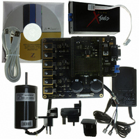
Z8FMC160100KITG Zilog, Z8FMC160100KITG Datasheet - Page 179

Z8FMC160100KITG
Manufacturer Part Number
Z8FMC160100KITG
Description
KIT DEV FOR Z8 ENCORE Z8FMC16100
Manufacturer
Zilog
Series
Z8 Encore! MC™r
Datasheets
1.Z8FMC160100KIT.pdf
(7 pages)
2.Z8FMC160100KIT.pdf
(383 pages)
3.Z8FMC160100KITG.pdf
(2 pages)
4.Z8FMC160100KITG.pdf
(15 pages)
Specifications of Z8FMC160100KITG
Main Purpose
Power Management, Motor Control
Embedded
Yes, MCU, 8-Bit
Utilized Ic / Part
Z8FMC16100
Primary Attributes
3-Ph DC Motors
Secondary Attributes
Graphical User Interface
For Use With
269-4664 - KIT ACC OPTO-ISO USB SMART CABLE269-4661 - KIT ACC ETHERNET SMART CABLE269-4539 - KIT ACCESSORY USB SMART CABLE
Lead Free Status / RoHS Status
Lead free / RoHS Compliant
Other names
269-4660
- Z8FMC160100KIT PDF datasheet
- Z8FMC160100KIT PDF datasheet #2
- Z8FMC160100KITG PDF datasheet #3
- Z8FMC160100KITG PDF datasheet #4
- Current page: 179 of 383
- Download datasheet (5Mb)
PS024613-0910
Start and Stop Conditions
Software Control of I
Master Transactions
The master generates the START and STOP conditions to start or end a transaction. To
start a transaction, the I
nal Low while SCL is High. To complete a transaction, the I
STOP
signal is High. These START and STOP events occur when the
the I
transfer currently under way, including the Acknowledge phase, finishes before the
START or
The I
MODE[1:0]
for MASTER/SLAVE or SLAVE ONLY mode, and configures the slave for 7- or 10-bit
addressing recognition.
MASTER/SLAVE mode can be used for:
•
•
•
In SLAVE ONLY mode, the START bit of the I
cannot initiate a master transaction by accident), and operation to SLAVE ONLY mode is
restricted, thereby preventing accidental operation in MASTER mode.
The software can control I
interrupt controller or by polling the I
To use interrupts, the I
by executing an EI instruction. The
enable transmit interrupts. An I
ister to determine the cause of the interrupt.
To control transactions by polling, the
rupt bits in the I
state of the
The following sections describe master Read and Write transactions to both 7-bit and
10-bit slaves.
MASTER ONLY operation in a single master/one or more slave I
MASTER/SLAVE in a multimaster/multislave I
SLAVE ONLY operation in an I
2
C Control register are written by software to begin or end a transaction. Any byte
2
condition by creating a Low-to-High transition of the SDA signal while the SCL
C controller is configured via the I
STOP
TXI
field of the I
2
bit.
condition occurs.
C Status register should be polled. The
2
2
C interrupt must be enabled in the interrupt controller and followed
2
C controller generates a
C Transactions
2
C Mode register allows the configuration of the I
2
C transactions by enabling the I
2
C interrupt service routine then checks the I
2
2
C system
TXI
C Status register.
TDRE
bit in the I
,
2
RDRF
C Control and I
START
2
C Control register is ignored (software
,
2
SAM
Z8FMC16100 Series Flash MCU
C system
2
C Control register must be set to
condition by pulling the SDA sig-
,
TDRE
ARBLST
2
C controller interrupt in the
bit asserts regardless of the
2
2
Product Specification
C controller generates a
C Mode registers. The
START
,
Start and Stop Conditions
SPRS
2
C system
, and
and
2
2
C Status reg-
STOP
C controller
NCKI
bits in
inter-
167
Related parts for Z8FMC160100KITG
Image
Part Number
Description
Manufacturer
Datasheet
Request
R

Part Number:
Description:
Communication Controllers, ZILOG INTELLIGENT PERIPHERAL CONTROLLER (ZIP)
Manufacturer:
Zilog, Inc.
Datasheet:

Part Number:
Description:
KIT DEV FOR Z8 ENCORE 16K TO 64K
Manufacturer:
Zilog
Datasheet:

Part Number:
Description:
KIT DEV Z8 ENCORE XP 28-PIN
Manufacturer:
Zilog
Datasheet:

Part Number:
Description:
DEV KIT FOR Z8 ENCORE 8K/4K
Manufacturer:
Zilog
Datasheet:

Part Number:
Description:
KIT DEV Z8 ENCORE XP 28-PIN
Manufacturer:
Zilog
Datasheet:

Part Number:
Description:
DEV KIT FOR Z8 ENCORE 4K TO 8K
Manufacturer:
Zilog
Datasheet:

Part Number:
Description:
CMOS Z8 microcontroller. ROM 16 Kbytes, RAM 256 bytes, speed 16 MHz, 32 lines I/O, 3.0V to 5.5V
Manufacturer:
Zilog, Inc.
Datasheet:

Part Number:
Description:
Low-cost microcontroller. 512 bytes ROM, 61 bytes RAM, 8 MHz
Manufacturer:
Zilog, Inc.
Datasheet:

Part Number:
Description:
Z8 4K OTP Microcontroller
Manufacturer:
Zilog, Inc.
Datasheet:

Part Number:
Description:
CMOS SUPER8 ROMLESS MCU
Manufacturer:
Zilog, Inc.
Datasheet:

Part Number:
Description:
SL1866 CMOSZ8 OTP Microcontroller
Manufacturer:
Zilog, Inc.
Datasheet:

Part Number:
Description:
SL1866 CMOSZ8 OTP Microcontroller
Manufacturer:
Zilog, Inc.
Datasheet:

Part Number:
Description:
OTP (KB) = 1, RAM = 125, Speed = 12, I/O = 14, 8-bit Timers = 2, Comm Interfaces Other Features = Por, LV Protect, Voltage = 4.5-5.5V
Manufacturer:
Zilog, Inc.
Datasheet:

Part Number:
Description:
Manufacturer:
Zilog, Inc.
Datasheet:


