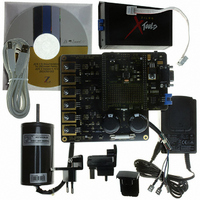
Z8FMC160100KITG Zilog, Z8FMC160100KITG Datasheet - Page 37

Z8FMC160100KITG
Manufacturer Part Number
Z8FMC160100KITG
Description
KIT DEV FOR Z8 ENCORE Z8FMC16100
Manufacturer
Zilog
Series
Z8 Encore! MC™r
Datasheets
1.Z8FMC160100KIT.pdf
(7 pages)
2.Z8FMC160100KIT.pdf
(383 pages)
3.Z8FMC160100KITG.pdf
(2 pages)
4.Z8FMC160100KITG.pdf
(15 pages)
Specifications of Z8FMC160100KITG
Main Purpose
Power Management, Motor Control
Embedded
Yes, MCU, 8-Bit
Utilized Ic / Part
Z8FMC16100
Primary Attributes
3-Ph DC Motors
Secondary Attributes
Graphical User Interface
For Use With
269-4664 - KIT ACC OPTO-ISO USB SMART CABLE269-4661 - KIT ACC ETHERNET SMART CABLE269-4539 - KIT ACCESSORY USB SMART CABLE
Lead Free Status / RoHS Status
Lead free / RoHS Compliant
Other names
269-4660
- Z8FMC160100KIT PDF datasheet
- Z8FMC160100KIT PDF datasheet #2
- Z8FMC160100KITG PDF datasheet #3
- Z8FMC160100KITG PDF datasheet #4
- Current page: 37 of 383
- Download datasheet (5Mb)
PS024613-0910
Stop Mode Recovery
External Reset Indicator
On-Chip Debugger Initiated Reset
Fault Detect Logic Reset
continues to be held in the Reset state. If the RESET pin is held Low beyond the System
Reset timeout, the device exits the Reset state 16 system clock cycles following RESET
pin deassertion. If the RESET pin is released before the System Reset timeout, the RESET
pin is driven Low by the chip until the completion of the timeout as described in the next
section. In STOP mode the digital filter is bypassed because the System Clock is disabled.
Following a System Reset initiated by the external RESET pin, the EXT status bit in the
Reset Status and Control Register
During System Reset, the RESET pin functions as an open-drain (active Low) reset mode
indicator in addition to the input functionality. This reset output feature allows a
Z8FMC16100 Series Flash MCU device to reset other connected components , even if the
reset is caused by internal sources such as POR, VBO, or WDT events and as an indication
of when the reset sequence completes.
After an internal reset event occurs, the internal circuitry begins driving the RESET pin
Low. The RESET pin is held Low by the internal circuitry until the appropriate delay
listed in
A System Reset may be initiated through the OCD by setting
register. The OCD is not reset but the rest of the chip goes through a normal System Reset.
The
POR
Fault detect circuitry exists to detect illegal state changes which may be caused by
transient power or electrostatic discharge events. When such a fault is detected, a system
reset is forced. Following the system reset, the
Register
The STOP mode is entered by execution of a
detailed STOP mode information, see
Recovery, the device is held in reset for 66 cycles of the IPO. Stop Mode Recovery only
affects the contents of the
ter. Stop Mode Recovery does not affect any other values in the Register File, including
the Stack Pointer, Register Pointer, Flags, peripheral control registers, and general-
purpose RAM.
RST
bit in the
Table 6
is set.
bit automatically clears during the system reset. Following the system reset, the
Reset Status and Control Register
has elapsed.
Reset Status and Control Register
is set to 1.
Low-Power Modes
is set.
FLTD
STOP
Z8FMC16100 Series Flash MCU
bit in the
instruction by the eZ8 CPU. For
on page 29. During Stop Mode
and
RST
Product Specification
Reset Status and Control
Oscillator Control Regis-
bit of the OCDCTL
External Reset Indicator
25
Related parts for Z8FMC160100KITG
Image
Part Number
Description
Manufacturer
Datasheet
Request
R

Part Number:
Description:
Communication Controllers, ZILOG INTELLIGENT PERIPHERAL CONTROLLER (ZIP)
Manufacturer:
Zilog, Inc.
Datasheet:

Part Number:
Description:
KIT DEV FOR Z8 ENCORE 16K TO 64K
Manufacturer:
Zilog
Datasheet:

Part Number:
Description:
KIT DEV Z8 ENCORE XP 28-PIN
Manufacturer:
Zilog
Datasheet:

Part Number:
Description:
DEV KIT FOR Z8 ENCORE 8K/4K
Manufacturer:
Zilog
Datasheet:

Part Number:
Description:
KIT DEV Z8 ENCORE XP 28-PIN
Manufacturer:
Zilog
Datasheet:

Part Number:
Description:
DEV KIT FOR Z8 ENCORE 4K TO 8K
Manufacturer:
Zilog
Datasheet:

Part Number:
Description:
CMOS Z8 microcontroller. ROM 16 Kbytes, RAM 256 bytes, speed 16 MHz, 32 lines I/O, 3.0V to 5.5V
Manufacturer:
Zilog, Inc.
Datasheet:

Part Number:
Description:
Low-cost microcontroller. 512 bytes ROM, 61 bytes RAM, 8 MHz
Manufacturer:
Zilog, Inc.
Datasheet:

Part Number:
Description:
Z8 4K OTP Microcontroller
Manufacturer:
Zilog, Inc.
Datasheet:

Part Number:
Description:
CMOS SUPER8 ROMLESS MCU
Manufacturer:
Zilog, Inc.
Datasheet:

Part Number:
Description:
SL1866 CMOSZ8 OTP Microcontroller
Manufacturer:
Zilog, Inc.
Datasheet:

Part Number:
Description:
SL1866 CMOSZ8 OTP Microcontroller
Manufacturer:
Zilog, Inc.
Datasheet:

Part Number:
Description:
OTP (KB) = 1, RAM = 125, Speed = 12, I/O = 14, 8-bit Timers = 2, Comm Interfaces Other Features = Por, LV Protect, Voltage = 4.5-5.5V
Manufacturer:
Zilog, Inc.
Datasheet:

Part Number:
Description:
Manufacturer:
Zilog, Inc.
Datasheet:


