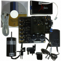
Z8FMC160100KITG Zilog, Z8FMC160100KITG Datasheet - Page 39

Z8FMC160100KITG
Manufacturer Part Number
Z8FMC160100KITG
Description
KIT DEV FOR Z8 ENCORE Z8FMC16100
Manufacturer
Zilog
Series
Z8 Encore! MC™r
Datasheets
1.Z8FMC160100KIT.pdf
(7 pages)
2.Z8FMC160100KIT.pdf
(383 pages)
3.Z8FMC160100KITG.pdf
(2 pages)
4.Z8FMC160100KITG.pdf
(15 pages)
Specifications of Z8FMC160100KITG
Main Purpose
Power Management, Motor Control
Embedded
Yes, MCU, 8-Bit
Utilized Ic / Part
Z8FMC16100
Primary Attributes
3-Ph DC Motors
Secondary Attributes
Graphical User Interface
For Use With
269-4664 - KIT ACC OPTO-ISO USB SMART CABLE269-4661 - KIT ACC ETHERNET SMART CABLE269-4539 - KIT ACCESSORY USB SMART CABLE
Lead Free Status / RoHS Status
Lead free / RoHS Compliant
Other names
269-4660
- Z8FMC160100KIT PDF datasheet
- Z8FMC160100KIT PDF datasheet #2
- Z8FMC160100KITG PDF datasheet #3
- Z8FMC160100KITG PDF datasheet #4
- Current page: 39 of 383
- Download datasheet (5Mb)
Table 9. Reset Status and Control Register (RSTSTAT)
BITS
FIELD
RESET
R/W
ADDR
PS024613-0910
Reset Control Register Definitions
Note:
Reset Status and Control Register
POR
R
7
Writing the
unlocks access to the
bit. The following sequence is required to unlock this register and write the
1. Write
2. Write
3. Write the
All steps of the unlock sequence must be written in the order listed.
The Reset Status and Control register
or Stop Mode Recovery. All status bits are updated on each Reset or Stop Mode Recovery
event.
Stop Mode Recovery event. The RESET pin function is also select with
The
function is selected by writing the unlock sequence followed by the mode to this register.
A software write to the
the
0 = RESET/Fault0 pin is configured as RESET input.
1 = RESET/Fault0 pin is configured as Fault0 input.
If the
the
location is unprogrammed (1) then after reset, the
to 0.
FLTSEL
FLTSEL
FLTSEL
FLTSEL
Table 10
STOP
14h
92h
R
6
14h
bit 7 in the User Flash Option2 byte location.
bit 0 in the RSTSTAT is set to 1. If the
FLTSEL
bit in this register allows software selection of the RESET pin. The pin
bit 7 in the Flash Option2 location is programmed to 0 then after reset,
to the Reset Status and Control register (RSTSTAT).
to the Reset Status and Control register (RSTSTAT).
indicates the possible states of the Reset status bits following a Reset or
,
See
92h
WDT
FLTSEL
Table 10
bit.
unlock sequence to the Reset Status and Control register address
R
5
FLTSEL
bit. The locking mechanism prevents spurious writes to this
bit 0 in the RSTSTAT register overrides the value set by
EXT
R
4
(Table
FF0H
9) records the cause of the most recent Reset
FLT
R
3
FLTSEL
FLTSEL
Z8FMC16100 Series Flash MCU
Reset Control Register Definitions
bit 7 in the Flash Option2
bit 0 in the RSTSTAT is set
2
Reserved
Product Specification
R
1
FLTSEL
FLTSEL
FLTSEL
bit.
R/W
0
u
bit:
27
Related parts for Z8FMC160100KITG
Image
Part Number
Description
Manufacturer
Datasheet
Request
R

Part Number:
Description:
Communication Controllers, ZILOG INTELLIGENT PERIPHERAL CONTROLLER (ZIP)
Manufacturer:
Zilog, Inc.
Datasheet:

Part Number:
Description:
KIT DEV FOR Z8 ENCORE 16K TO 64K
Manufacturer:
Zilog
Datasheet:

Part Number:
Description:
KIT DEV Z8 ENCORE XP 28-PIN
Manufacturer:
Zilog
Datasheet:

Part Number:
Description:
DEV KIT FOR Z8 ENCORE 8K/4K
Manufacturer:
Zilog
Datasheet:

Part Number:
Description:
KIT DEV Z8 ENCORE XP 28-PIN
Manufacturer:
Zilog
Datasheet:

Part Number:
Description:
DEV KIT FOR Z8 ENCORE 4K TO 8K
Manufacturer:
Zilog
Datasheet:

Part Number:
Description:
CMOS Z8 microcontroller. ROM 16 Kbytes, RAM 256 bytes, speed 16 MHz, 32 lines I/O, 3.0V to 5.5V
Manufacturer:
Zilog, Inc.
Datasheet:

Part Number:
Description:
Low-cost microcontroller. 512 bytes ROM, 61 bytes RAM, 8 MHz
Manufacturer:
Zilog, Inc.
Datasheet:

Part Number:
Description:
Z8 4K OTP Microcontroller
Manufacturer:
Zilog, Inc.
Datasheet:

Part Number:
Description:
CMOS SUPER8 ROMLESS MCU
Manufacturer:
Zilog, Inc.
Datasheet:

Part Number:
Description:
SL1866 CMOSZ8 OTP Microcontroller
Manufacturer:
Zilog, Inc.
Datasheet:

Part Number:
Description:
SL1866 CMOSZ8 OTP Microcontroller
Manufacturer:
Zilog, Inc.
Datasheet:

Part Number:
Description:
OTP (KB) = 1, RAM = 125, Speed = 12, I/O = 14, 8-bit Timers = 2, Comm Interfaces Other Features = Por, LV Protect, Voltage = 4.5-5.5V
Manufacturer:
Zilog, Inc.
Datasheet:

Part Number:
Description:
Manufacturer:
Zilog, Inc.
Datasheet:


