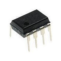
PIC12F1840-I/P Microchip Technology, PIC12F1840-I/P Datasheet - Page 201

PIC12F1840-I/P
Manufacturer Part Number
PIC12F1840-I/P
Description
7 KB Flash, 256 Bytes RAM, 32 MHz Int. Osc, 6 I/0, Enhanced Mid Range Core 8 PDI
Manufacturer
Microchip Technology
Datasheet
1.PIC12F1840-IP.pdf
(382 pages)
Specifications of PIC12F1840-I/P
Processor Series
PIC12F
Core
PIC
Program Memory Type
Flash
Program Memory Size
7 KB
Data Ram Size
256 B
Interface Type
MI2C, SPI, EUSART
Number Of Timers
3
Operating Supply Voltage
1.8 V to 5.5 V
Maximum Operating Temperature
+ 85 C
Mounting Style
Through Hole
Package / Case
PDIP-8
Development Tools By Supplier
MPLAB IDE Software
Minimum Operating Temperature
- 40 C
Lead Free Status / Rohs Status
Lead free / RoHS Compliant
Available stocks
Company
Part Number
Manufacturer
Quantity
Price
Company:
Part Number:
PIC12F1840-I/P
Manufacturer:
MICROCHIP
Quantity:
200
- Current page: 201 of 382
- Download datasheet (4Mb)
24.4.2
The PWM mode supports an Auto-Shutdown mode that
will disable the PWM outputs when an external
shutdown event occurs. Auto-Shutdown mode places
the PWM output pins into a predetermined state. This
mode is used to help prevent the PWM from damaging
the application.
The auto-shutdown sources are selected using the
CCP1AS<2:0> bits of the CCP1AS register. A shutdown
event may be generated by:
• A logic ‘0’ on the INT pin
• Comparator C1
• Setting the CCP1ASE bit in firmware
A shutdown condition is indicated by the CCP1ASE
(Auto-Shutdown Event Status) bit of the CCP1AS
register. If the bit is a ‘0’, the PWM pins are operating
normally. If the bit is a ‘1’, the PWM outputs are in the
shutdown state.
When a shutdown event occurs, two things happen:
The CCP1ASE bit is set to ‘1’. The CCP1ASE will
remain set until cleared in firmware or an auto-restart
occurs (see
FIGURE 24-10:
2011 Microchip Technology Inc.
Shutdown
PWM
CCP1ASE bit
ENHANCED PWM AUTO-
SHUTDOWN MODE
Section 24.4.3 “Auto-Restart
Activity
Event
PWM AUTO-SHUTDOWN WITH FIRMWARE RESTART (P1RSEN = 0)
Overflow
Timer
Start of
PWM Period
PWM Period
(Auto-Shutdown)
Mode”).
Event Occurs
Missing Pulse
Overflow
Shutdown
Timer
Preliminary
Event Clears
Shutdown
Overflow
The enabled PWM pins are asynchronously placed in
their shutdown states. The PWM output pins are
grouped into pairs [P1A] and [P1B. The state of each pin
pair is determined by the PSS1AC and PSS1BD bits of
the CCP1AS register. Each pin pair may be placed into
one of three states:
• Drive logic ‘1’
• Drive logic ‘0’
• Tri-state (high-impedance)
Timer
Note 1: The auto-shutdown condition is a level-
2: Writing to the CCP1ASE bit is disabled
3: Once the auto-shutdown condition has
Missing Pulse
(CCP1ASE not clear)
based signal, not an edge-based signal.
As long as the level is present, the auto-
shutdown will persist.
while
persists.
been removed and the PWM restarted
(either through firmware or auto-restart)
the PWM signal will always restart at the
beginning of the next PWM period.
Overflow
Cleared by
CCP1ASE
Firmware
Timer
PIC12(L)F1840
an
PWM
Resumes
auto-shutdown
Overflow
DS41441B-page 201
Timer
condition
Related parts for PIC12F1840-I/P
Image
Part Number
Description
Manufacturer
Datasheet
Request
R

Part Number:
Description:
7 KB Flash, 256 Bytes RAM, 32 MHz Int. Osc, 6 I/0, Enhanced Mid Range Core, Nano
Manufacturer:
Microchip Technology
Datasheet:

Part Number:
Description:
MCU, MPU & DSP Development Tools 8 Bit PIC Develop Microcontroller
Manufacturer:
SchmartBoard
Datasheet:

Part Number:
Description:
7 KB Flash, 256 Bytes RAM, 32 MHz Int. Osc, 6 I/0, Enhanced Mid Range Core 8 DFN
Manufacturer:
Microchip Technology

Part Number:
Description:
7 KB Flash, 256 Bytes RAM, 32 MHz Int. Osc, 6 I/0, Enhanced Mid Range Core 8 SOI
Manufacturer:
Microchip Technology

Part Number:
Description:
7 KB Flash, 256 Bytes RAM, 32 MHz Int. Osc, 6 I/0, Enhanced Mid Range Core, Nano
Manufacturer:
Microchip Technology
Datasheet:

Part Number:
Description:
7 KB Flash, 256 Bytes RAM, 32 MHz Int. Osc, 6 I/0, Enhanced Mid Range Core, Nano
Manufacturer:
Microchip Technology
Datasheet:

Part Number:
Description:
7 KB Flash, 256 Bytes RAM, 32 MHz Int. Osc, 6 I/0, Enhanced Mid Range Core, Nano
Manufacturer:
Microchip Technology
Datasheet:

Part Number:
Description:
7 KB Flash, 256 Bytes RAM, 32 MHz Int. Osc, 6 I/0, Enhanced Mid Range Core, Nano
Manufacturer:
Microchip Technology

Part Number:
Description:
7 KB Flash, 256 Bytes RAM, 32 MHz Int. Osc, 6 I/0, Enhanced Mid Range Core, Nano
Manufacturer:
Microchip Technology

Part Number:
Description:
7 KB Flash, 256 Bytes RAM, 32 MHz Int. Osc, 6 I/0, Enhanced Mid Range Core, Nano
Manufacturer:
Microchip Technology
Datasheet:

Part Number:
Description:
7 KB Flash, 256 Bytes RAM, 32 MHz Int. Osc, 6 I/0, Enhanced Mid Range Core, Nano
Manufacturer:
Microchip Technology
Datasheet:

Part Number:
Description:
Manufacturer:
Microchip Technology Inc.
Datasheet:

Part Number:
Description:
Manufacturer:
Microchip Technology Inc.
Datasheet:


