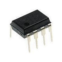
PIC12F1840-I/P Microchip Technology, PIC12F1840-I/P Datasheet - Page 237

PIC12F1840-I/P
Manufacturer Part Number
PIC12F1840-I/P
Description
7 KB Flash, 256 Bytes RAM, 32 MHz Int. Osc, 6 I/0, Enhanced Mid Range Core 8 PDI
Manufacturer
Microchip Technology
Datasheet
1.PIC12F1840-IP.pdf
(382 pages)
Specifications of PIC12F1840-I/P
Processor Series
PIC12F
Core
PIC
Program Memory Type
Flash
Program Memory Size
7 KB
Data Ram Size
256 B
Interface Type
MI2C, SPI, EUSART
Number Of Timers
3
Operating Supply Voltage
1.8 V to 5.5 V
Maximum Operating Temperature
+ 85 C
Mounting Style
Through Hole
Package / Case
PDIP-8
Development Tools By Supplier
MPLAB IDE Software
Minimum Operating Temperature
- 40 C
Lead Free Status / Rohs Status
Lead free / RoHS Compliant
Available stocks
Company
Part Number
Manufacturer
Quantity
Price
Company:
Part Number:
PIC12F1840-I/P
Manufacturer:
MICROCHIP
Quantity:
200
- Current page: 237 of 382
- Download datasheet (4Mb)
25.5.4
This section describes a standard sequence of events
for the MSSP1 module configured as an I
10-bit Addressing mode.
Figure 25-19
description.
This is a step by step process of what must be done by
slave software to accomplish I
1.
2.
3.
4.
5.
6.
7.
8.
9.
10. Slave clears SSP1IF.
11. Slave reads the received matching address
12. Slave loads high address into SSP1ADD.
13. Master clocks a data byte to the slave and
14. If SEN bit of SSP1CON2 is set, CKP is cleared
15. Slave clears SSP1IF.
16. Slave reads the received byte from SSP1BUF
17. If SEN is set the slave sets CKP to release the
18. Steps 13-17 repeat for each received byte.
19. Master sends Stop to end the transmission.
2011 Microchip Technology Inc.
Note: Updates to the SSP1ADD register are not
Note: If the low address does not match, SSP1IF
Bus starts Idle.
Master
SSP1STAT is set; SSP1IF is set if inter-
rupt-on-Start detect is enabled.
Master sends matching high address with R/W
bit clear; UA bit of the SSP1STAT register is set.
Slave sends ACK and SSP1IF is set.
Software clears the SSP1IF bit.
Software
SSP1BUF clearing the BF flag.
Slave loads low address into SSP1ADD,
releasing SCL.
Master sends matching low address byte to the
Slave; UA bit is set.
Slave sends ACK and SSP1IF is set.
from SSP1BUF clearing BF.
clocks out the slaves ACK on the 9th SCL pulse;
SSP1IF is set.
by hardware and the clock is stretched.
clearing BF.
SCL.
SLAVE MODE 10-BIT ADDRESS
RECEPTION
allowed until after the ACK sequence.
and UA are still set so that the slave soft-
ware can set SSP1ADD back to the high
address. BF is not set because there is no
match. CKP is unaffected.
sends
is used as a visual reference for this
reads
Start
received
condition;
2
C communication.
address
S
2
C Slave in
bit
from
of
Preliminary
25.5.5
Reception using 10-bit addressing with AHEN or
DHEN set is the same as with 7-bit modes. The only
difference is the need to update the SSP1ADD register
using the UA bit. All functionality, specifically when the
CKP bit is cleared and SCL line is held low are the
same.
slave in 10-bit addressing with AHEN set.
Figure 25-21
transmitter in 10-bit Addressing mode.
Figure 25-20
10-BIT ADDRESSING WITH ADDRESS OR
DATA HOLD
shows a standard waveform for a slave
PIC12(L)F1840
can be used as a reference of a
DS41441B-page 237
Related parts for PIC12F1840-I/P
Image
Part Number
Description
Manufacturer
Datasheet
Request
R

Part Number:
Description:
7 KB Flash, 256 Bytes RAM, 32 MHz Int. Osc, 6 I/0, Enhanced Mid Range Core, Nano
Manufacturer:
Microchip Technology
Datasheet:

Part Number:
Description:
MCU, MPU & DSP Development Tools 8 Bit PIC Develop Microcontroller
Manufacturer:
SchmartBoard
Datasheet:

Part Number:
Description:
7 KB Flash, 256 Bytes RAM, 32 MHz Int. Osc, 6 I/0, Enhanced Mid Range Core 8 DFN
Manufacturer:
Microchip Technology

Part Number:
Description:
7 KB Flash, 256 Bytes RAM, 32 MHz Int. Osc, 6 I/0, Enhanced Mid Range Core 8 SOI
Manufacturer:
Microchip Technology

Part Number:
Description:
7 KB Flash, 256 Bytes RAM, 32 MHz Int. Osc, 6 I/0, Enhanced Mid Range Core, Nano
Manufacturer:
Microchip Technology
Datasheet:

Part Number:
Description:
7 KB Flash, 256 Bytes RAM, 32 MHz Int. Osc, 6 I/0, Enhanced Mid Range Core, Nano
Manufacturer:
Microchip Technology
Datasheet:

Part Number:
Description:
7 KB Flash, 256 Bytes RAM, 32 MHz Int. Osc, 6 I/0, Enhanced Mid Range Core, Nano
Manufacturer:
Microchip Technology
Datasheet:

Part Number:
Description:
7 KB Flash, 256 Bytes RAM, 32 MHz Int. Osc, 6 I/0, Enhanced Mid Range Core, Nano
Manufacturer:
Microchip Technology

Part Number:
Description:
7 KB Flash, 256 Bytes RAM, 32 MHz Int. Osc, 6 I/0, Enhanced Mid Range Core, Nano
Manufacturer:
Microchip Technology

Part Number:
Description:
7 KB Flash, 256 Bytes RAM, 32 MHz Int. Osc, 6 I/0, Enhanced Mid Range Core, Nano
Manufacturer:
Microchip Technology
Datasheet:

Part Number:
Description:
7 KB Flash, 256 Bytes RAM, 32 MHz Int. Osc, 6 I/0, Enhanced Mid Range Core, Nano
Manufacturer:
Microchip Technology
Datasheet:

Part Number:
Description:
Manufacturer:
Microchip Technology Inc.
Datasheet:

Part Number:
Description:
Manufacturer:
Microchip Technology Inc.
Datasheet:


