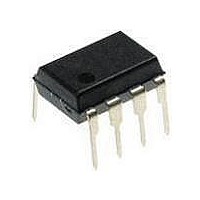
PIC12F1840-I/P Microchip Technology, PIC12F1840-I/P Datasheet - Page 246

PIC12F1840-I/P
Manufacturer Part Number
PIC12F1840-I/P
Description
7 KB Flash, 256 Bytes RAM, 32 MHz Int. Osc, 6 I/0, Enhanced Mid Range Core 8 PDI
Manufacturer
Microchip Technology
Datasheet
1.PIC12F1840-IP.pdf
(382 pages)
Specifications of PIC12F1840-I/P
Processor Series
PIC12F
Core
PIC
Program Memory Type
Flash
Program Memory Size
7 KB
Data Ram Size
256 B
Interface Type
MI2C, SPI, EUSART
Number Of Timers
3
Operating Supply Voltage
1.8 V to 5.5 V
Maximum Operating Temperature
+ 85 C
Mounting Style
Through Hole
Package / Case
PDIP-8
Development Tools By Supplier
MPLAB IDE Software
Minimum Operating Temperature
- 40 C
Lead Free Status / Rohs Status
Lead free / RoHS Compliant
Available stocks
Company
Part Number
Manufacturer
Quantity
Price
Company:
Part Number:
PIC12F1840-I/P
Manufacturer:
MICROCHIP
Quantity:
200
- Current page: 246 of 382
- Download datasheet (4Mb)
PIC12(L)F1840
25.6.5
A Repeated Start condition occurs when the RSEN bit
of the SSP1CON2 register is programmed high and the
Master state machine is no longer active. When the
RSEN bit is set, the SCL pin is asserted low. When the
SCL pin is sampled low, the Baud Rate Generator is
loaded and begins counting. The SDA pin is released
(brought high) for one Baud Rate Generator count
(Tpwrt). When the Baud Rate Generator times out, if
SDA is sampled high, the SCL pin will be deasserted
(brought high). When SCL is sampled high, the Baud
Rate Generator is reloaded and begins counting. SDA
and SCL must be sampled high for one Tpwrt. This
action is then followed by assertion of the SDA pin
(SDA = 0) for one Tpwrt while SCL is high. SCL is
asserted low. Following this, the RSEN bit of the
FIGURE 25-27:
DS41441B-page 246
I
START CONDITION TIMING
2
C MASTER MODE REPEATED
REPEAT START CONDITION WAVEFORM
SDA
SCL
Write to SSP1CON2
occurs here
SDA = 1,
SCL (no change)
Preliminary
T
BRG
SDA = 1,
SCL = 1
T
BRG
Repeated Start
SSP1CON2 register will be automatically cleared and
the Baud Rate Generator will not be reloaded, leaving
the SDA pin held low. As soon as a Start condition is
detected on the SDA and SCL pins, the S bit of the
SSP1STAT register will be set. The SSP1IF bit will not
be set until the Baud Rate Generator has timed out.
Sr
Note 1: If RSEN is programmed while any other
T
BRG
2: A bus collision during the Repeated Start
S bit set by hardware
At completion of Start bit,
hardware clears RSEN bit
Write to SSP1BUF occurs here
event is in progress, it will not take effect.
condition occurs if:
and sets SSP1IF
• SDA is sampled low when SCL
• SCL goes low before SDA is
T
BRG
goes from low-to-high.
asserted low. This may indicate
that another master is attempting to
transmit a data ‘1’.
1st bit
T
BRG
2011 Microchip Technology Inc.
Related parts for PIC12F1840-I/P
Image
Part Number
Description
Manufacturer
Datasheet
Request
R

Part Number:
Description:
7 KB Flash, 256 Bytes RAM, 32 MHz Int. Osc, 6 I/0, Enhanced Mid Range Core, Nano
Manufacturer:
Microchip Technology
Datasheet:

Part Number:
Description:
MCU, MPU & DSP Development Tools 8 Bit PIC Develop Microcontroller
Manufacturer:
SchmartBoard
Datasheet:

Part Number:
Description:
7 KB Flash, 256 Bytes RAM, 32 MHz Int. Osc, 6 I/0, Enhanced Mid Range Core 8 DFN
Manufacturer:
Microchip Technology

Part Number:
Description:
7 KB Flash, 256 Bytes RAM, 32 MHz Int. Osc, 6 I/0, Enhanced Mid Range Core 8 SOI
Manufacturer:
Microchip Technology

Part Number:
Description:
7 KB Flash, 256 Bytes RAM, 32 MHz Int. Osc, 6 I/0, Enhanced Mid Range Core, Nano
Manufacturer:
Microchip Technology
Datasheet:

Part Number:
Description:
7 KB Flash, 256 Bytes RAM, 32 MHz Int. Osc, 6 I/0, Enhanced Mid Range Core, Nano
Manufacturer:
Microchip Technology
Datasheet:

Part Number:
Description:
7 KB Flash, 256 Bytes RAM, 32 MHz Int. Osc, 6 I/0, Enhanced Mid Range Core, Nano
Manufacturer:
Microchip Technology
Datasheet:

Part Number:
Description:
7 KB Flash, 256 Bytes RAM, 32 MHz Int. Osc, 6 I/0, Enhanced Mid Range Core, Nano
Manufacturer:
Microchip Technology

Part Number:
Description:
7 KB Flash, 256 Bytes RAM, 32 MHz Int. Osc, 6 I/0, Enhanced Mid Range Core, Nano
Manufacturer:
Microchip Technology

Part Number:
Description:
7 KB Flash, 256 Bytes RAM, 32 MHz Int. Osc, 6 I/0, Enhanced Mid Range Core, Nano
Manufacturer:
Microchip Technology
Datasheet:

Part Number:
Description:
7 KB Flash, 256 Bytes RAM, 32 MHz Int. Osc, 6 I/0, Enhanced Mid Range Core, Nano
Manufacturer:
Microchip Technology
Datasheet:

Part Number:
Description:
Manufacturer:
Microchip Technology Inc.
Datasheet:

Part Number:
Description:
Manufacturer:
Microchip Technology Inc.
Datasheet:


