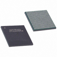
EP3C25F324I7 Altera, EP3C25F324I7 Datasheet - Page 103

EP3C25F324I7
Manufacturer Part Number
EP3C25F324I7
Description
IC CYCLONE III FPGA 25K 324 FBGA
Manufacturer
Altera
Series
Cyclone® IIIr
Datasheets
1.EP3C5F256C8N.pdf
(5 pages)
2.EP3C5F256C8N.pdf
(34 pages)
3.EP3C5F256C8N.pdf
(66 pages)
4.EP3C5F256C8N.pdf
(14 pages)
5.EP3C5F256C8N.pdf
(76 pages)
6.EP3C25F324I7.pdf
(274 pages)
Specifications of EP3C25F324I7
Number Of Logic Elements/cells
24624
Number Of Labs/clbs
1539
Total Ram Bits
608256
Number Of I /o
215
Voltage - Supply
1.15 V ~ 1.25 V
Mounting Type
Surface Mount
Operating Temperature
-40°C ~ 100°C
Package / Case
324-FBGA
Family Name
Cyclone III
Number Of Logic Blocks/elements
24624
# I/os (max)
215
Frequency (max)
437.5MHz
Process Technology
65nm
Operating Supply Voltage (typ)
1.2V
Logic Cells
24624
Ram Bits
608256
Operating Supply Voltage (min)
1.15V
Operating Supply Voltage (max)
1.25V
Operating Temp Range
-40C to 100C
Operating Temperature Classification
Industrial
Mounting
Surface Mount
Pin Count
324
Package Type
FBGA
For Use With
544-2370 - KIT STARTER CYCLONE III EP3C25
Lead Free Status / RoHS Status
Contains lead / RoHS non-compliant
Number Of Gates
-
Lead Free Status / Rohs Status
Not Compliant
Available stocks
Company
Part Number
Manufacturer
Quantity
Price
Company:
Part Number:
EP3C25F324I7N
Manufacturer:
ALTERA32
Quantity:
181
Chapter 6: I/O Features in the Cyclone III Device Family
I/O Element Features
© December 2009
f
f
1
Altera Corporation
For more information about programmable current strength, refer to the
Editor
Table 6–1
These programmable current strength settings are a valuable tool in helping decrease
the effects of simultaneously switching outputs (SSO) in conjunction with reducing
system noise. The supported settings ensure that the device driver meets the
specifications for IOH and IOL of the corresponding I/O standard.
When you use programmable current strength, on-chip series termination is not
available.
Table 6–1. Programmable Current Strength
For information about how to interface the Cyclone III device family with 3.3-, 3.0-, or
2.5-V systems, refer to the guidelines provided in
Devices with 3.3/3.0/2.5-V LVTTL/LVCMOS I/O
1.2-V LVCMOS
1.5-V LVCMOS
1.8-V LVTTL/LVCMOS
2.5-V LVTTL/LVCMOS
3.0-V LVCMOS
3.0-V LVTTL
3.3-V LVCMOS
3.3-V LVTTL
HSTL-12 Class I
HSTL-12 Class II
HSTL-15 Class I
HSTL-15 Class II
HSTL-18 Class I
HSTL-18 Class II
SSTL-18 Class I
SSTL-18 Class II
SSTL-2 Class I
SSTL-2 Class II
BLVDS
Notes to
(1) The default setting in the Quartus II software is 50-Ω OCT without calibration for all non-voltage reference and
(2) The default current setting in the Quartus II software is highlighted in bold italic for 3.3-V LVTTL and 3.3-V LVCMOS
HSTL/SSTL Class I I/O standards. The default setting is 25-Ω OCT without calibration for HSTL/SSTL Class II I/O
standards.
I/O standards.
chapter in volume 2 of the Quartus II Handbook.
Table
I/O Standard
lists the possible settings for I/O standards with current strength control.
(2)
6–1:
(2)
Top and Bottom I/O Pins
2, 4, 6, 8, 10, 12,16
2, 4, 6, 8, 10, 12,16
2, 4, 6, 8, 10,12
4, 8, 12,16
4, 8, 12,16
4, 8, 12,16
8, 10, 12
8, 10, 12
8, 10, 12
8, 12, 16
8, 10,12
(Note 1)
12, 16
8, 12
4, 8
14
16
16
16
I
2
O H
/I
OL
Systems.
Current Strength Setting (mA)
AN 447: Interfacing Cyclone III
Cyclone III Device Handbook, Volume 1
Left and Right I/O Pins
2, 4, 6, 8, 10, 12,16
2, 4, 6, 8, 10, 12,16
2, 4, 6, 8,10
4, 8, 12,16
4, 8, 12,16
4, 8, 12,16
8, 10, 12
8, 10, 12
8, 10, 12
8, 12, 16
12, 16
8, 10
8, 12
4, 8
—
16
16
16
2
Assignment
6–3


