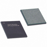
EP3C25F324I7 Altera, EP3C25F324I7 Datasheet - Page 219

EP3C25F324I7
Manufacturer Part Number
EP3C25F324I7
Description
IC CYCLONE III FPGA 25K 324 FBGA
Manufacturer
Altera
Series
Cyclone® IIIr
Datasheets
1.EP3C5F256C8N.pdf
(5 pages)
2.EP3C5F256C8N.pdf
(34 pages)
3.EP3C5F256C8N.pdf
(66 pages)
4.EP3C5F256C8N.pdf
(14 pages)
5.EP3C5F256C8N.pdf
(76 pages)
6.EP3C25F324I7.pdf
(274 pages)
Specifications of EP3C25F324I7
Number Of Logic Elements/cells
24624
Number Of Labs/clbs
1539
Total Ram Bits
608256
Number Of I /o
215
Voltage - Supply
1.15 V ~ 1.25 V
Mounting Type
Surface Mount
Operating Temperature
-40°C ~ 100°C
Package / Case
324-FBGA
Family Name
Cyclone III
Number Of Logic Blocks/elements
24624
# I/os (max)
215
Frequency (max)
437.5MHz
Process Technology
65nm
Operating Supply Voltage (typ)
1.2V
Logic Cells
24624
Ram Bits
608256
Operating Supply Voltage (min)
1.15V
Operating Supply Voltage (max)
1.25V
Operating Temp Range
-40C to 100C
Operating Temperature Classification
Industrial
Mounting
Surface Mount
Pin Count
324
Package Type
FBGA
For Use With
544-2370 - KIT STARTER CYCLONE III EP3C25
Lead Free Status / RoHS Status
Contains lead / RoHS non-compliant
Number Of Gates
-
Lead Free Status / Rohs Status
Not Compliant
Available stocks
Company
Part Number
Manufacturer
Quantity
Price
Company:
Part Number:
EP3C25F324I7N
Manufacturer:
ALTERA32
Quantity:
181
Chapter 9: Configuration, Design Security, and Remote System Upgrades in the Cyclone III Device Family
Configuration Features
© December 2009
Altera Corporation
Programming Serial Configuration Devices In-System Using the JTAG Interface
Cyclone III device family in a single-device or in a multiple-device chain supports
in-system programming of a serial configuration device with the JTAG interface using
the SFL design. The intelligent host or download cable of the board can use the four
JTAG pins on the Cyclone III device family to program the serial configuration device
in system, even if the host or download cable cannot access the configuration pins
(DCLK, DATA, ASDI, and nCS pins).
The SFL design is a JTAG-based in-system programming solution for Altera serial
configuration devices. The SFL is a bridge design for the Cyclone III device family
that uses its JTAG interface to access the EPCS JTAG Indirect Configuration Device
Programming (.jic) file and then uses the AS interface to program the EPCS device.
Both the JTAG interface and AS interface are bridged together inside the SFL design.
In a multiple device chain, you must only configure the master device that controls
the serial configuration device. When using this feature, the slave devices in the
multiple device chain which are configured by the serial configuration device do not
need to be configured. To use this feature successfully, set the MSEL[3..0]pins of the
master device to select the AS configuration scheme
serial configuration device in-system programming through the Cyclone III device
family JTAG interface has three stages, which are described in the following sections:
■
■
■
Loading the SFL Design
The SFL design is a design inside the Cyclone III device family that bridges the JTAG
interface and the AS interface with glue logic.
The intelligent host uses the JTAG interface to configure the master device with a SFL
design. The SFL design allows the master device to control the access of four serial
configuration device pins, also known as the Active Serial Memory Interface (ASMI)
pins, through the JTAG interface. The ASMI pins are serial clock input (DCLK), serial
data output (DATA), AS data input (ASDI), and active-low chip select (nCS) pins.
If you configure a master device with a SFL design, the master device enters user
mode even though the slave devices in the multiple device chain are not being
configured. The master device enters user mode with a SFL design even though the
CONF_DONE signal is externally held low by the other slave devices in chain.
Figure 9–30
SFL design.
“Loading the SFL Design” on page 9–59
“ISP of the Configuration Device” on page 9–60
“Reconfiguration” on page 9–61
shows the JTAG configuration of a single Cyclone III device family with a
(Table 9–7 on page
Cyclone III Device Handbook, Volume 1
9–11). The
9–59


