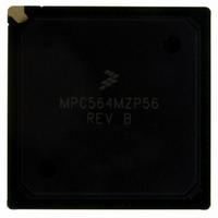
MPC564MZP56 Freescale Semiconductor, MPC564MZP56 Datasheet - Page 106

MPC564MZP56
Manufacturer Part Number
MPC564MZP56
Description
IC MCU 512K FLASH 56MHZ 388-BGA
Manufacturer
Freescale Semiconductor
Series
MPC5xxr
Specifications of MPC564MZP56
Core Processor
PowerPC
Core Size
32-Bit
Speed
56MHz
Connectivity
CAN, EBI/EMI, SCI, SPI, UART/USART
Peripherals
POR, PWM, WDT
Number Of I /o
56
Program Memory Size
512KB (512K x 8)
Program Memory Type
FLASH
Ram Size
32K x 8
Voltage - Supply (vcc/vdd)
2.5 V ~ 2.7 V
Data Converters
A/D 32x10b
Oscillator Type
External
Operating Temperature
-40°C ~ 125°C
Package / Case
388-BGA
Core
PowerPC
Processor Series
MPC5xx
Data Bus Width
32 bit
Maximum Clock Frequency
56 MHz
Data Ram Size
32 KB
On-chip Adc
Yes
Number Of Programmable I/os
56
Number Of Timers
2
Operating Supply Voltage
0 V to 5 V
Mounting Style
SMD/SMT
A/d Bit Size
10 bit
A/d Channels Available
32
Height
1.95 mm
Interface Type
CAN, JTAG, QSPI, SCI, SPI, UART
Length
27 mm
Maximum Operating Temperature
+ 125 C
Minimum Operating Temperature
- 40 C
Supply Voltage (max)
2.7 V, 5.25 V
Supply Voltage (min)
2.5 V, 4.75 V
Width
27 mm
For Use With
MPC564EVB - KIT EVAL FOR MPC561/562/563/564
Lead Free Status / RoHS Status
Contains lead / RoHS non-compliant
Eeprom Size
-
Lead Free Status / Rohs Status
No RoHS Version Available
Available stocks
Company
Part Number
Manufacturer
Quantity
Price
Company:
Part Number:
MPC564MZP56
Manufacturer:
FREESCAL
Quantity:
364
Company:
Part Number:
MPC564MZP56
Manufacturer:
Freescale Semiconductor
Quantity:
10 000
Part Number:
MPC564MZP56
Manufacturer:
FREESCALE
Quantity:
20 000
Company:
Part Number:
MPC564MZP56R2
Manufacturer:
Freescale Semiconductor
Quantity:
10 000
- Current page: 106 of 1420
- Download datasheet (11Mb)
Signal Descriptions
2-8
BG / VF0 / LWP1
BR / VF1 / IWP2
BB / VF2 / IWP3
IWP[0:1] / VFLS[0:1]
Signal Name
Table 2-1. MPC561/MPC563 Signal Descriptions (continued)
Signals
No. of
1
1
1
2
MPC561/MPC563 Reference Manual, Rev. 1.2
Type
I/O
I/O
I/O
O
O
O
O
O
O
O
O
Controlled by
RCW[DBGC].
See
Controlled by
RCW[DBGC].
See
Controlled by
RCW[DBGC].
See
Controlled by
RCW[DBGC].
See
Function after
Reset
Table
Table
Table 6-8
Table
6-8.
6-8.
6-8.
1
Bus Grant. Indicates external bus status. BG is asserted low
when the external bus arbiter grants ownership of the
external bus to a specific master. This is an active-low signal
and needs an external pull-up resistor to ensure proper
operation and meet signal timing specifications.
Visible Instruction Queue Flush Status 0. This output signal
together with VF1 and VF2 is output by the
MPC561/MPC563 when program instruction flow tracking is
required. VFs report the number of instructions flushed from
the instruction queue in the internal core. See
“Development
Load/Store Watchpoint 1. This output signal reports the
detection of a data watchpoint in the program flow executed
by the RCPU.
Bus Request. Indicates that the external bus has been
requested for external cycle. This is an active-low signal and
needs an external pull-up resistor to ensure proper
operation and meet signal timing specifications.
Visible Instruction Queue Flush Status 1. This output signal
together with VF0 and VF2 is output by the
MPC561/MPC563 when program instruction flow tracking is
required. VFs report the number of instructions flushed from
the instruction queue in the internal core. See
“Development
Instruction Watchpoint 2. This output signal reports the
detection of an instruction watchpoint in the program flow
executed by the RCPU.
Bus Busy. Indicates that the master is using the external
bus. BB is an active-low signal and needs an external
pull-up resistor to ensure proper operation and signal timing
specifications.
Visible Instruction Queue Flush Status 2. This output signal
together with VF0 and VF1 is output by the
MPC561/MPC563 when a program instructions flow
tracking is required. VFs report the number of instructions
flushed from the instruction queue in the internal core.
Instruction Watchpoint 3. This output signal reports the
detection of an instruction watchpoint in the program flow
executed by the internal core.
Instruction Watchpoint [0:1]. These output signals report the
detection of an instruction watchpoint in the program flow
executed by the RCPU.
Visible History Buffer Flush Status [0:1]. These signals are
output by the MPC561/MPC563 to enable program
instruction flow tracking. They report the number of
instructions flushed from the history buffer in the RCPU. See
Chapter 23, “Development
Support,” for more details.
Support,” for more details.
Description
Support,” for details.
Freescale Semiconductor
Chapter 23,
Chapter 23,
Related parts for MPC564MZP56
Image
Part Number
Description
Manufacturer
Datasheet
Request
R

Part Number:
Description:
MPC5 1K0 5%
Manufacturer:
TE Connectivity
Datasheet:

Part Number:
Description:
MPC5 500R 5%
Manufacturer:
TE Connectivity
Datasheet:

Part Number:
Description:
MPC5 5K0 5%
Manufacturer:
Tyco Electronics
Datasheet:

Part Number:
Description:
MPC5 5R0 5%
Manufacturer:
Tyco Electronics
Datasheet:

Part Number:
Description:
MPC5 50K 5%
Manufacturer:
Tyco Electronics
Datasheet:

Part Number:
Description:
MPC5 1R0 5%
Manufacturer:
Tyco Electronics
Datasheet:
Part Number:
Description:
Manufacturer:
Freescale Semiconductor, Inc
Datasheet:
Part Number:
Description:
Manufacturer:
Freescale Semiconductor, Inc
Datasheet:
Part Number:
Description:
Manufacturer:
Freescale Semiconductor, Inc
Datasheet:
Part Number:
Description:
Manufacturer:
Freescale Semiconductor, Inc
Datasheet:
Part Number:
Description:
Manufacturer:
Freescale Semiconductor, Inc
Datasheet:


