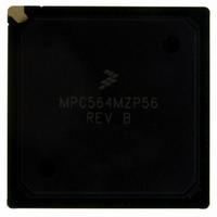
MPC564MZP56 Freescale Semiconductor, MPC564MZP56 Datasheet - Page 440

MPC564MZP56
Manufacturer Part Number
MPC564MZP56
Description
IC MCU 512K FLASH 56MHZ 388-BGA
Manufacturer
Freescale Semiconductor
Series
MPC5xxr
Specifications of MPC564MZP56
Core Processor
PowerPC
Core Size
32-Bit
Speed
56MHz
Connectivity
CAN, EBI/EMI, SCI, SPI, UART/USART
Peripherals
POR, PWM, WDT
Number Of I /o
56
Program Memory Size
512KB (512K x 8)
Program Memory Type
FLASH
Ram Size
32K x 8
Voltage - Supply (vcc/vdd)
2.5 V ~ 2.7 V
Data Converters
A/D 32x10b
Oscillator Type
External
Operating Temperature
-40°C ~ 125°C
Package / Case
388-BGA
Core
PowerPC
Processor Series
MPC5xx
Data Bus Width
32 bit
Maximum Clock Frequency
56 MHz
Data Ram Size
32 KB
On-chip Adc
Yes
Number Of Programmable I/os
56
Number Of Timers
2
Operating Supply Voltage
0 V to 5 V
Mounting Style
SMD/SMT
A/d Bit Size
10 bit
A/d Channels Available
32
Height
1.95 mm
Interface Type
CAN, JTAG, QSPI, SCI, SPI, UART
Length
27 mm
Maximum Operating Temperature
+ 125 C
Minimum Operating Temperature
- 40 C
Supply Voltage (max)
2.7 V, 5.25 V
Supply Voltage (min)
2.5 V, 4.75 V
Width
27 mm
For Use With
MPC564EVB - KIT EVAL FOR MPC561/562/563/564
Lead Free Status / RoHS Status
Contains lead / RoHS non-compliant
Eeprom Size
-
Lead Free Status / Rohs Status
No RoHS Version Available
Available stocks
Company
Part Number
Manufacturer
Quantity
Price
Company:
Part Number:
MPC564MZP56
Manufacturer:
FREESCAL
Quantity:
364
Company:
Part Number:
MPC564MZP56
Manufacturer:
Freescale Semiconductor
Quantity:
10 000
Part Number:
MPC564MZP56
Manufacturer:
FREESCALE
Quantity:
20 000
Company:
Part Number:
MPC564MZP56R2
Manufacturer:
Freescale Semiconductor
Quantity:
10 000
- Current page: 440 of 1420
- Download datasheet (11Mb)
L-Bus to U-Bus Interface (L2U)
When a load to or store from the U-bus resource is issued by the RCPU, it is compared against the DMPU
region access (address and attribute) comparators. If none of the access attributes are violated, the access
is directed to the U-bus by the L2U module. If the DMPU detects an access violation, it informs the error
status to the master initiating the cycle.
When show cycles are enabled, accesses to all of the L-bus resources by the RCPU are made visible on
the U-bus side by the L2U.
The L2U is responsible for handling the effects of reservations on the L-bus and the U-bus. For the L-bus
and the U-bus, the L2U detects reservation losses and updates the RCPU core with the reservation status.
11.4.2
While hard or soft reset is asserted on the U-bus, the L2U asserts the corresponding L-bus reset signals.
Upon soft reset assertion, the L2U goes to an idle state and all pending accesses are ignored. Additionally,
the L2U module control registers are not initialized on soft reset, keeping the system configuration
unchanged.
Upon assertion of hard reset, the L2U control registers are initialized to their reset states. The L2U also
drives the reset configuration word from the U-bus to the L-bus upon hard reset.
11.4.3
In the peripheral mode of operation the RCPU is shut down and an alternative master on the external bus
can perform accesses to any internal bus (U-bus and L-bus) slave.
The external master can also access the internal MPC500 special registers that are located in the L2U
module. In order to access one of these MPC500 registers the EMCR[CONT] bit in the USIU must be
cleared.
11.4.4
Factory test mode is a special mode of operation that allows access to the internal modules for testing. This
mode is not intended for general use and is not supported for normal applications.
11.5
The data memory protection unit (DMPU) in the L2U module provides access protection for the memory
regions on the U-bus side from load/store accesses by the RCPU. (Only U-bus space is protected.) The
DMPU does not protect MPC500 register accesses initiated by the RCPU on the L-bus. The user can assign
up to four regions of access protection attributes and can assign global attributes to any space not included
in the active regions. When it detects an access violation, the L2U generates an exception request to the
CPU. A functional diagram of the DMPU is shown in
11-4
Data Memory Protection
Reset Operation
Peripheral Mode
Factory Test Mode
MPC561/MPC563 Reference Manual, Rev. 1.2
Figure
11-2.
Freescale Semiconductor
Related parts for MPC564MZP56
Image
Part Number
Description
Manufacturer
Datasheet
Request
R

Part Number:
Description:
MPC5 1K0 5%
Manufacturer:
TE Connectivity
Datasheet:

Part Number:
Description:
MPC5 500R 5%
Manufacturer:
TE Connectivity
Datasheet:

Part Number:
Description:
MPC5 5K0 5%
Manufacturer:
Tyco Electronics
Datasheet:

Part Number:
Description:
MPC5 5R0 5%
Manufacturer:
Tyco Electronics
Datasheet:

Part Number:
Description:
MPC5 50K 5%
Manufacturer:
Tyco Electronics
Datasheet:

Part Number:
Description:
MPC5 1R0 5%
Manufacturer:
Tyco Electronics
Datasheet:
Part Number:
Description:
Manufacturer:
Freescale Semiconductor, Inc
Datasheet:
Part Number:
Description:
Manufacturer:
Freescale Semiconductor, Inc
Datasheet:
Part Number:
Description:
Manufacturer:
Freescale Semiconductor, Inc
Datasheet:
Part Number:
Description:
Manufacturer:
Freescale Semiconductor, Inc
Datasheet:
Part Number:
Description:
Manufacturer:
Freescale Semiconductor, Inc
Datasheet:


