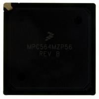
MPC564MZP56 Freescale Semiconductor, MPC564MZP56 Datasheet - Page 668

MPC564MZP56
Manufacturer Part Number
MPC564MZP56
Description
IC MCU 512K FLASH 56MHZ 388-BGA
Manufacturer
Freescale Semiconductor
Series
MPC5xxr
Specifications of MPC564MZP56
Core Processor
PowerPC
Core Size
32-Bit
Speed
56MHz
Connectivity
CAN, EBI/EMI, SCI, SPI, UART/USART
Peripherals
POR, PWM, WDT
Number Of I /o
56
Program Memory Size
512KB (512K x 8)
Program Memory Type
FLASH
Ram Size
32K x 8
Voltage - Supply (vcc/vdd)
2.5 V ~ 2.7 V
Data Converters
A/D 32x10b
Oscillator Type
External
Operating Temperature
-40°C ~ 125°C
Package / Case
388-BGA
Core
PowerPC
Processor Series
MPC5xx
Data Bus Width
32 bit
Maximum Clock Frequency
56 MHz
Data Ram Size
32 KB
On-chip Adc
Yes
Number Of Programmable I/os
56
Number Of Timers
2
Operating Supply Voltage
0 V to 5 V
Mounting Style
SMD/SMT
A/d Bit Size
10 bit
A/d Channels Available
32
Height
1.95 mm
Interface Type
CAN, JTAG, QSPI, SCI, SPI, UART
Length
27 mm
Maximum Operating Temperature
+ 125 C
Minimum Operating Temperature
- 40 C
Supply Voltage (max)
2.7 V, 5.25 V
Supply Voltage (min)
2.5 V, 4.75 V
Width
27 mm
For Use With
MPC564EVB - KIT EVAL FOR MPC561/562/563/564
Lead Free Status / RoHS Status
Contains lead / RoHS non-compliant
Eeprom Size
-
Lead Free Status / Rohs Status
No RoHS Version Available
Available stocks
Company
Part Number
Manufacturer
Quantity
Price
Company:
Part Number:
MPC564MZP56
Manufacturer:
FREESCAL
Quantity:
364
Company:
Part Number:
MPC564MZP56
Manufacturer:
Freescale Semiconductor
Quantity:
10 000
Part Number:
MPC564MZP56
Manufacturer:
FREESCALE
Quantity:
20 000
Company:
Part Number:
MPC564MZP56R2
Manufacturer:
Freescale Semiconductor
Quantity:
10 000
- Current page: 668 of 1420
- Download datasheet (11Mb)
Queued Serial Multi-Channel Module
15.7.5
The SCxDR consists of two data registers located at the same address. The receive data register (RDRx)
is a read-only register that contains data received by the SCI serial interface. Data is shifted into the receive
serial shifter and is transferred to RDRx. The transmit data register (TDRx) is a write-only register that
contains data to be transmitted. Data is first written to TDRx, then transferred to the transmit serial shifter,
where additional format bits are added before transmission.
15-50
Bits
12
13
14
15
SCI Data Register (SCxDR)
Name
OR
NF
FE
PF
Overrun error. OR is set when a new byte is ready to be transferred from the receive serial shifter
to register RDRx, and RDRx is already full (RDRF is still set). Data transfer is inhibited until OR
is cleared. Previous data in RDRx remains valid, but additional data received during an overrun
condition (including the byte that set OR) is lost.
Note that whereas the other receiver status flags (NF, FE, and PF) reflect the status of data
already transferred to RDRx, the OR flag reflects an operational condition that resulted in a loss
of data to RDRx.
0 RDRF is cleared before new data arrives.
1 RDRF is not cleared before new data arrives.
Noise error flag. NF is set when the receiver detects noise on a valid start bit, on any of the data
bits, or on the stop bit(s). It is not set by noise on the idle line or on invalid start bits. Each bit is
sampled three times for noise. If the three samples are not at the same logic level, the majority
value is used for the received data value, and NF is set. NF is not set until the entire frame is
received and RDRF is set.
Although no interrupt is explicitly associated with NF, an interrupt can be generated with RDRF,
and the interrupt handler can check NF.
0 No noise detected in the received data.
1 Noise detected in the received data.
For receiver queue operation NF is cleared when SCxSR is read with NF set, followed by a read
of SCRQ[0:15].
Framing error. FE is set when the receiver detects a zero where a stop bit (one) was expected.
A framing error results when the frame boundaries in the received bit stream are not
synchronized with the receiver bit counter. FE is not set until the entire frame is received and
RDRF is set.
Although no interrupt is explicitly associated with FE, an interrupt can be generated with RDRF,
and the interrupt handler can check FE.
0 No framing error detected in the received data.
1 Framing error or break detected in the received data.
Parity error. PF is set when the receiver detects a parity error. PF is not set until the entire frame
is received and RDRF is set.
Although no interrupt is explicitly associated with PF, an interrupt can be generated with RDRF,
and the interrupt handler can check PF.
0 No parity error detected in the received data.
1 Parity error detected in the received data.
Table 15-26. SCxSR Bit Descriptions (continued)
MPC561/MPC563 Reference Manual, Rev. 1.2
Description
Freescale Semiconductor
Related parts for MPC564MZP56
Image
Part Number
Description
Manufacturer
Datasheet
Request
R

Part Number:
Description:
MPC5 1K0 5%
Manufacturer:
TE Connectivity
Datasheet:

Part Number:
Description:
MPC5 500R 5%
Manufacturer:
TE Connectivity
Datasheet:

Part Number:
Description:
MPC5 5K0 5%
Manufacturer:
Tyco Electronics
Datasheet:

Part Number:
Description:
MPC5 5R0 5%
Manufacturer:
Tyco Electronics
Datasheet:

Part Number:
Description:
MPC5 50K 5%
Manufacturer:
Tyco Electronics
Datasheet:

Part Number:
Description:
MPC5 1R0 5%
Manufacturer:
Tyco Electronics
Datasheet:
Part Number:
Description:
Manufacturer:
Freescale Semiconductor, Inc
Datasheet:
Part Number:
Description:
Manufacturer:
Freescale Semiconductor, Inc
Datasheet:
Part Number:
Description:
Manufacturer:
Freescale Semiconductor, Inc
Datasheet:
Part Number:
Description:
Manufacturer:
Freescale Semiconductor, Inc
Datasheet:
Part Number:
Description:
Manufacturer:
Freescale Semiconductor, Inc
Datasheet:


