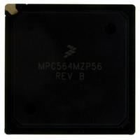
MPC564MZP56 Freescale Semiconductor, MPC564MZP56 Datasheet - Page 356

MPC564MZP56
Manufacturer Part Number
MPC564MZP56
Description
IC MCU 512K FLASH 56MHZ 388-BGA
Manufacturer
Freescale Semiconductor
Series
MPC5xxr
Specifications of MPC564MZP56
Core Processor
PowerPC
Core Size
32-Bit
Speed
56MHz
Connectivity
CAN, EBI/EMI, SCI, SPI, UART/USART
Peripherals
POR, PWM, WDT
Number Of I /o
56
Program Memory Size
512KB (512K x 8)
Program Memory Type
FLASH
Ram Size
32K x 8
Voltage - Supply (vcc/vdd)
2.5 V ~ 2.7 V
Data Converters
A/D 32x10b
Oscillator Type
External
Operating Temperature
-40°C ~ 125°C
Package / Case
388-BGA
Core
PowerPC
Processor Series
MPC5xx
Data Bus Width
32 bit
Maximum Clock Frequency
56 MHz
Data Ram Size
32 KB
On-chip Adc
Yes
Number Of Programmable I/os
56
Number Of Timers
2
Operating Supply Voltage
0 V to 5 V
Mounting Style
SMD/SMT
A/d Bit Size
10 bit
A/d Channels Available
32
Height
1.95 mm
Interface Type
CAN, JTAG, QSPI, SCI, SPI, UART
Length
27 mm
Maximum Operating Temperature
+ 125 C
Minimum Operating Temperature
- 40 C
Supply Voltage (max)
2.7 V, 5.25 V
Supply Voltage (min)
2.5 V, 4.75 V
Width
27 mm
For Use With
MPC564EVB - KIT EVAL FOR MPC561/562/563/564
Lead Free Status / RoHS Status
Contains lead / RoHS non-compliant
Eeprom Size
-
Lead Free Status / Rohs Status
No RoHS Version Available
Available stocks
Company
Part Number
Manufacturer
Quantity
Price
Company:
Part Number:
MPC564MZP56
Manufacturer:
FREESCAL
Quantity:
364
Company:
Part Number:
MPC564MZP56
Manufacturer:
Freescale Semiconductor
Quantity:
10 000
Part Number:
MPC564MZP56
Manufacturer:
FREESCALE
Quantity:
20 000
Company:
Part Number:
MPC564MZP56R2
Manufacturer:
Freescale Semiconductor
Quantity:
10 000
- Current page: 356 of 1420
- Download datasheet (11Mb)
External Bus Interface
memory to three-state the bus before the bus discharge is initiated. EHTR has a slight performance
reduction impact since it adds a clock gap between some read and write cycles.
9.5.3.1
Pre-discharge mode should be enabled in the following cases:
9.5.3.2
Systems that require pre-discharge operation should include the following steps:
9-16
•
•
•
•
•
•
When external devices can charge the data bus to a higher voltage level than 3.1 volts
And when one or more of the following occurs:
— The MPC561/MPC563 uses write accesses to any external memory
— Data show cycles are enabled
— Instruction show cycles are enabled in code compression mode (MPC562/MPC564 only)
Execute boot sequence
Set EHTR bit in all relevant memory banks during the memory controller initialization phase
(configure ORx, and BRx) if it is required to extend the time between read cycles, and
pre-discharge phase of write cycles.
Set PREDIS_EN in PDMCR2 register
Start to write data to external devices
Operating Conditions
Initialization Sequence
EHTR also adds one idle clock for two consecutive read cycles from
different memory banks.
The pre-disharge will not occur, when using multiple processors with a
common bus accessing an external device, if the processor that initiates a
read is different from the processor that initiated the previous write. Perform
a write to the external device to discharge the external bus, or read a value
of 0x0 from the external device, prior to accessing another MCU on the
same bus.
In the case of code compression program tracking (3rd case above), the
PREDIS_EN bit should only be set when program tracking is not required
since pre-discharge mode overwrites the compression show cycles data. The
user should not set PREDIS_EN bit when program tracking is required on
development system, and set PREDIS_EN bit on the production version.
EHTR can always be set to keep the same system performance during
development, and production phases.
MPC561/MPC563 Reference Manual, Rev. 1.2
NOTE
NOTE
NOTE
Freescale Semiconductor
Related parts for MPC564MZP56
Image
Part Number
Description
Manufacturer
Datasheet
Request
R

Part Number:
Description:
MPC5 1K0 5%
Manufacturer:
TE Connectivity
Datasheet:

Part Number:
Description:
MPC5 500R 5%
Manufacturer:
TE Connectivity
Datasheet:

Part Number:
Description:
MPC5 5K0 5%
Manufacturer:
Tyco Electronics
Datasheet:

Part Number:
Description:
MPC5 5R0 5%
Manufacturer:
Tyco Electronics
Datasheet:

Part Number:
Description:
MPC5 50K 5%
Manufacturer:
Tyco Electronics
Datasheet:

Part Number:
Description:
MPC5 1R0 5%
Manufacturer:
Tyco Electronics
Datasheet:
Part Number:
Description:
Manufacturer:
Freescale Semiconductor, Inc
Datasheet:
Part Number:
Description:
Manufacturer:
Freescale Semiconductor, Inc
Datasheet:
Part Number:
Description:
Manufacturer:
Freescale Semiconductor, Inc
Datasheet:
Part Number:
Description:
Manufacturer:
Freescale Semiconductor, Inc
Datasheet:
Part Number:
Description:
Manufacturer:
Freescale Semiconductor, Inc
Datasheet:


