DF61654N50FTV Renesas Electronics America, DF61654N50FTV Datasheet - Page 27
DF61654N50FTV
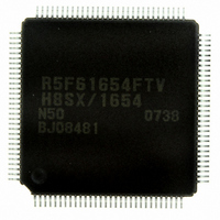
Manufacturer Part Number
DF61654N50FTV
Description
IC H8SX/1654 MCU FLASH 120TQFP
Manufacturer
Renesas Electronics America
Series
H8® H8SX/1600r
Datasheet
1.DF61653N50FTV.pdf
(1020 pages)
Specifications of DF61654N50FTV
Core Processor
H8SX
Core Size
32-Bit
Speed
50MHz
Connectivity
I²C, IrDA, SCI, SmartCard, USB
Peripherals
DMA, PWM, WDT
Number Of I /o
75
Program Memory Size
512KB (512K x 8)
Program Memory Type
FLASH
Ram Size
40K x 8
Voltage - Supply (vcc/vdd)
3 V ~ 3.6 V
Data Converters
A/D 8x10b; D/A 2x8b
Oscillator Type
External
Operating Temperature
-20°C ~ 75°C
Package / Case
120-TQFP, 120-VQFP
For Use With
HS0005KCU11H - EMULATOR E10A-USB H8S(X),SH2(A)3DK1657 - DEV EVAL KIT FOR H8SX/1657
Lead Free Status / RoHS Status
Lead free / RoHS Compliant
Eeprom Size
-
Available stocks
Company
Part Number
Manufacturer
Quantity
Price
Company:

Part Number:
DF61654N50FTV
Manufacturer:
Renesas Electronics America
Quantity:
10 000


20.11 Standard Serial Communication Interface Specifications for Boot Mode ......................... 816
20.12 Usage Notes ....................................................................................................................... 841
Section 21 Clock Pulse Generator .....................................................................843
21.1 Register Description........................................................................................................... 845
21.2 Oscillator............................................................................................................................ 848
21.3 PLL Circuit ........................................................................................................................ 850
21.4 Frequency Divider ............................................................................................................. 850
21.5 Usage Notes ....................................................................................................................... 850
Section 22 Power-Down Modes ........................................................................853
22.1 Features.............................................................................................................................. 853
22.2 Register Descriptions ......................................................................................................... 855
22.3 Multi-Clock Function......................................................................................................... 862
22.4 Sleep Mode ........................................................................................................................ 863
22.5 Software Standby Mode..................................................................................................... 864
22.6 Hardware Standby Mode ................................................................................................... 868
22.7 Module Stop Mode ............................................................................................................ 869
22.8 Sleep Interrupt Function..................................................................................................... 871
21.1.1 System Clock Control Register (SCKCR) ............................................................ 845
21.2.1 Connecting Crystal Resonator .............................................................................. 848
21.2.2 External Clock Input............................................................................................. 849
21.5.1 Notes on Clock Pulse Generator ........................................................................... 850
21.5.2 Notes on Resonator............................................................................................... 851
21.5.3 Notes on Board Design ......................................................................................... 852
22.2.1 Standby Control Register (SBYCR) ..................................................................... 856
22.2.2 Module Stop Control Registers A and B (MSTPCRA and MSTPCRB) .............. 858
22.2.3 Module Stop Control Register C (MSTPCRC)..................................................... 861
22.4.1 Transition to Sleep Mode...................................................................................... 863
22.4.2 Clearing Sleep Mode ............................................................................................ 863
22.5.1 Transition to Software Standby Mode .................................................................. 864
22.5.2 Clearing Software Standby Mode ......................................................................... 864
22.5.3 Setting Oscillation Settling Time after Clearing Software Standby Mode ........... 865
22.5.4 Software Standby Mode Application Example..................................................... 867
22.6.1 Transition to Hardware Standby Mode ................................................................. 868
22.6.2 Clearing Hardware Standby Mode........................................................................ 868
22.6.3 Hardware Standby Mode Timing.......................................................................... 868
22.6.4 Timing Sequence at Power-On ............................................................................. 869
22.7.1 Module Stop Mode ............................................................................................... 869
22.7.2 All-Module-Clock-Stop Mode.............................................................................. 870
Rev.1.00 Sep. 08, 2005 Page xxv of xlviiil
Related parts for DF61654N50FTV
Image
Part Number
Description
Manufacturer
Datasheet
Request
R

Part Number:
Description:
KIT STARTER FOR M16C/29
Manufacturer:
Renesas Electronics America
Datasheet:

Part Number:
Description:
KIT STARTER FOR R8C/2D
Manufacturer:
Renesas Electronics America
Datasheet:

Part Number:
Description:
R0K33062P STARTER KIT
Manufacturer:
Renesas Electronics America
Datasheet:

Part Number:
Description:
KIT STARTER FOR R8C/23 E8A
Manufacturer:
Renesas Electronics America
Datasheet:

Part Number:
Description:
KIT STARTER FOR R8C/25
Manufacturer:
Renesas Electronics America
Datasheet:

Part Number:
Description:
KIT STARTER H8S2456 SHARPE DSPLY
Manufacturer:
Renesas Electronics America
Datasheet:

Part Number:
Description:
KIT STARTER FOR R8C38C
Manufacturer:
Renesas Electronics America
Datasheet:

Part Number:
Description:
KIT STARTER FOR R8C35C
Manufacturer:
Renesas Electronics America
Datasheet:

Part Number:
Description:
KIT STARTER FOR R8CL3AC+LCD APPS
Manufacturer:
Renesas Electronics America
Datasheet:
Part Number:
Description:
KIT STARTER FOR RX610
Manufacturer:
Renesas Electronics America
Datasheet:

Part Number:
Description:
KIT STARTER FOR R32C/118
Manufacturer:
Renesas Electronics America
Datasheet:

Part Number:
Description:
KIT DEV RSK-R8C/26-29
Manufacturer:
Renesas Electronics America
Datasheet:

Part Number:
Description:
KIT STARTER FOR SH7124
Manufacturer:
Renesas Electronics America
Datasheet:

Part Number:
Description:
KIT STARTER FOR H8SX/1622
Manufacturer:
Renesas Electronics America
Datasheet:

Part Number:
Description:
KIT DEV FOR SH7203
Manufacturer:
Renesas Electronics America
Datasheet: