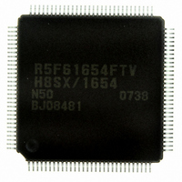
DF61654N50FTV Renesas Electronics America, DF61654N50FTV Datasheet - Page 37

DF61654N50FTV
Manufacturer Part Number
DF61654N50FTV
Description
IC H8SX/1654 MCU FLASH 120TQFP
Manufacturer
Renesas Electronics America
Series
H8® H8SX/1600r
Datasheet
1.DF61653N50FTV.pdf
(1020 pages)
Specifications of DF61654N50FTV
Core Processor
H8SX
Core Size
32-Bit
Speed
50MHz
Connectivity
I²C, IrDA, SCI, SmartCard, USB
Peripherals
DMA, PWM, WDT
Number Of I /o
75
Program Memory Size
512KB (512K x 8)
Program Memory Type
FLASH
Ram Size
40K x 8
Voltage - Supply (vcc/vdd)
3 V ~ 3.6 V
Data Converters
A/D 8x10b; D/A 2x8b
Oscillator Type
External
Operating Temperature
-20°C ~ 75°C
Package / Case
120-TQFP, 120-VQFP
For Use With
HS0005KCU11H - EMULATOR E10A-USB H8S(X),SH2(A)3DK1657 - DEV EVAL KIT FOR H8SX/1657
Lead Free Status / RoHS Status
Lead free / RoHS Compliant
Eeprom Size
-
Available stocks
Company
Part Number
Manufacturer
Quantity
Price
Company:
Part Number:
DF61654N50FTV
Manufacturer:
Renesas Electronics America
Quantity:
10 000
- Current page: 37 of 1020
- Download datasheet (6Mb)
Figure 14.41 Port Pin States during Mode Transition (Internal Clock, Clocked Synchronous
Figure 14.42 Sample Flowchart for Mode Transition during Reception .................................... 631
Figure 14.43 Block Diagram of CRC Operation Circuit ............................................................ 632
Figure 14.44 LSB-First Data Transmission ................................................................................ 635
Figure 14.45 MSB-First Data Transmission ............................................................................... 635
Figure 14.46 LSB-First Data Reception ..................................................................................... 636
Figure 14.47 MSB-First Data Reception .................................................................................... 637
Figure 14.48 LSB-First and MSB-First Transmit Data .............................................................. 638
Section 15 USB Function Module (USB)
Figure 15.1 Block Diagram of USB ........................................................................................... 640
Figure 15.2 Cable Connection Operation ................................................................................... 674
Figure 15.3 Cable Disconnection Operation............................................................................... 675
Figure 15.4 Suspend Operation .................................................................................................. 676
Figure 15.5 Resume Operation from Up-Stream ........................................................................ 677
Figure 15.6 Flow of Transition to and Canceling Software Standby Mode................................ 678
Figure 15.7 Timing of Transition to and Canceling Software Standby Mode ............................ 679
Figure 15.8 Remote-Wakeup...................................................................................................... 680
Figure 15.9 Transfer Stages in Control Transfer ........................................................................ 681
Figure 15.10 Setup Stage Operation ........................................................................................... 682
Figure 15.11 Data Stage (Control-In) Operation ........................................................................ 683
Figure 15.12 Data Stage (Control-Out) Operation...................................................................... 684
Figure 15.13 Status Stage (Control-In) Operation ...................................................................... 685
Figure 15.14 Status Stage (Control-Out) Operation ................................................................... 686
Figure 15.15 EP1 Bulk-Out Transfer Operation......................................................................... 687
Figure 15.16 EP2 Bulk-In Transfer Operation............................................................................ 688
Figure 15.17 Operation of EP3 Interrupt-In Transfer ................................................................. 690
Figure 15.18 Forcible Stall by Application................................................................................. 693
Figure 15.19 Automatic Stall by USB Function Module............................................................ 694
Figure 15.20 RDFN Bit Operation for EP1 ................................................................................ 695
Figure 15.21 PKTE Bit Operation for EP2................................................................................. 696
Figure 15.22 Example of Circuitry in Bus Power Mode ............................................................ 697
Figure 15.23 Example of Circuitry in Self Power Mode ............................................................ 698
Figure 15.24 TR Interrupt Flag Set Timing ................................................................................ 700
Section 16 I2C Bus Interface2 (IIC2)
Figure 16.1 Block Diagram of I
Figure 16.2 Connections to the External Circuit by the I/O Pins................................................ 705
Figure 16.3 I
Figure 16.4 I
2
2
Transmission) (Setting is Prohibited in SCI_5 and SCI_6) ................................... 631
C Bus Formats ...................................................................................................... 718
C Bus Timing........................................................................................................ 718
2
C Bus Interface2...................................................................... 704
Rev.1.00 Sep. 08, 2005 Page xxxv of xlviii
Related parts for DF61654N50FTV
Image
Part Number
Description
Manufacturer
Datasheet
Request
R

Part Number:
Description:
KIT STARTER FOR M16C/29
Manufacturer:
Renesas Electronics America
Datasheet:

Part Number:
Description:
KIT STARTER FOR R8C/2D
Manufacturer:
Renesas Electronics America
Datasheet:

Part Number:
Description:
R0K33062P STARTER KIT
Manufacturer:
Renesas Electronics America
Datasheet:

Part Number:
Description:
KIT STARTER FOR R8C/23 E8A
Manufacturer:
Renesas Electronics America
Datasheet:

Part Number:
Description:
KIT STARTER FOR R8C/25
Manufacturer:
Renesas Electronics America
Datasheet:

Part Number:
Description:
KIT STARTER H8S2456 SHARPE DSPLY
Manufacturer:
Renesas Electronics America
Datasheet:

Part Number:
Description:
KIT STARTER FOR R8C38C
Manufacturer:
Renesas Electronics America
Datasheet:

Part Number:
Description:
KIT STARTER FOR R8C35C
Manufacturer:
Renesas Electronics America
Datasheet:

Part Number:
Description:
KIT STARTER FOR R8CL3AC+LCD APPS
Manufacturer:
Renesas Electronics America
Datasheet:

Part Number:
Description:
KIT STARTER FOR RX610
Manufacturer:
Renesas Electronics America
Datasheet:

Part Number:
Description:
KIT STARTER FOR R32C/118
Manufacturer:
Renesas Electronics America
Datasheet:

Part Number:
Description:
KIT DEV RSK-R8C/26-29
Manufacturer:
Renesas Electronics America
Datasheet:

Part Number:
Description:
KIT STARTER FOR SH7124
Manufacturer:
Renesas Electronics America
Datasheet:

Part Number:
Description:
KIT STARTER FOR H8SX/1622
Manufacturer:
Renesas Electronics America
Datasheet:

Part Number:
Description:
KIT DEV FOR SH7203
Manufacturer:
Renesas Electronics America
Datasheet:


