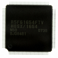
DF61654N50FTV Renesas Electronics America, DF61654N50FTV Datasheet - Page 43

DF61654N50FTV
Manufacturer Part Number
DF61654N50FTV
Description
IC H8SX/1654 MCU FLASH 120TQFP
Manufacturer
Renesas Electronics America
Series
H8® H8SX/1600r
Datasheet
1.DF61653N50FTV.pdf
(1020 pages)
Specifications of DF61654N50FTV
Core Processor
H8SX
Core Size
32-Bit
Speed
50MHz
Connectivity
I²C, IrDA, SCI, SmartCard, USB
Peripherals
DMA, PWM, WDT
Number Of I /o
75
Program Memory Size
512KB (512K x 8)
Program Memory Type
FLASH
Ram Size
40K x 8
Voltage - Supply (vcc/vdd)
3 V ~ 3.6 V
Data Converters
A/D 8x10b; D/A 2x8b
Oscillator Type
External
Operating Temperature
-20°C ~ 75°C
Package / Case
120-TQFP, 120-VQFP
For Use With
HS0005KCU11H - EMULATOR E10A-USB H8S(X),SH2(A)3DK1657 - DEV EVAL KIT FOR H8SX/1657
Lead Free Status / RoHS Status
Lead free / RoHS Compliant
Eeprom Size
-
Available stocks
Company
Part Number
Manufacturer
Quantity
Price
Company:
Part Number:
DF61654N50FTV
Manufacturer:
Renesas Electronics America
Quantity:
10 000
- Current page: 43 of 1020
- Download datasheet (6Mb)
Section 1 Overview
Table 1.1
Table 1.2
Section 2 CPU
Table 2.1
Table 2.2
Table 2.2
Table 2.3
Table 2.4
Table 2.5
Table 2.6
Table 2.7
Table 2.8
Table 2.9
Table 2.10
Table 2.11
Table 2.12
Table 2.13
Table 2.14
Table 2.15
Section 3 MCU Operating Modes
Table 3.1
Table 3.2
Table 3.3
Section 4 Exception Handling
Table 4.1
Table 4.2
Table 4.3
Table 4.4
Table 4.5
Table 4.6
Table 4.7
Table 4.8
Table 4.9
Pin Configuration in Each Operating Mode.............................................................. 4
Pin Functions ............................................................................................................ 8
Instruction Classification ........................................................................................ 34
Combinations of Instructions and Addressing Modes (1)....................................... 36
Combinations of Instructions and Addressing Modes (2)....................................... 39
Operation Notation ................................................................................................. 40
Data Transfer Instructions....................................................................................... 41
Block Transfer Instructions..................................................................................... 42
Arithmetic Operation Instructions .......................................................................... 43
Logic Operation Instructions .................................................................................. 45
Shift Operation Instructions.................................................................................... 45
Bit Manipulation Instructions ................................................................................. 46
Branch Instructions ................................................................................................. 48
System Control Instructions.................................................................................... 49
Addressing Modes .................................................................................................. 51
Absolute Address Access Ranges ........................................................................... 54
Effective Address Calculation for Transfer and Operation Instructions ................. 58
Effective Address Calculation for Branch Instructions........................................... 59
MCU Operating Mode Settings .............................................................................. 61
Settings of Bits MDS3 to MDS0............................................................................. 63
Pin Functions in Each Operating Mode (Advanced Mode) .................................... 68
Exception Types and Priority.................................................................................. 73
Exception Handling Vector Table........................................................................... 74
Calculation Method of Exception Handling Vector Table Address........................ 76
Status of CCR and EXR after Trace Exception Handling....................................... 79
Bus Cycle and Address Error.................................................................................. 80
Status of CCR and EXR after Address Error Exception Handling ......................... 81
Interrupt Sources..................................................................................................... 82
Status of CCR and EXR after Trap Instruction Exception Handling...................... 84
Status of CCR and EXR after Illegal Instruction Exception Handling ................... 85
Tables
Rev.1.00 Sep. 08, 2005 Page xli of xlviii
Related parts for DF61654N50FTV
Image
Part Number
Description
Manufacturer
Datasheet
Request
R

Part Number:
Description:
KIT STARTER FOR M16C/29
Manufacturer:
Renesas Electronics America
Datasheet:

Part Number:
Description:
KIT STARTER FOR R8C/2D
Manufacturer:
Renesas Electronics America
Datasheet:

Part Number:
Description:
R0K33062P STARTER KIT
Manufacturer:
Renesas Electronics America
Datasheet:

Part Number:
Description:
KIT STARTER FOR R8C/23 E8A
Manufacturer:
Renesas Electronics America
Datasheet:

Part Number:
Description:
KIT STARTER FOR R8C/25
Manufacturer:
Renesas Electronics America
Datasheet:

Part Number:
Description:
KIT STARTER H8S2456 SHARPE DSPLY
Manufacturer:
Renesas Electronics America
Datasheet:

Part Number:
Description:
KIT STARTER FOR R8C38C
Manufacturer:
Renesas Electronics America
Datasheet:

Part Number:
Description:
KIT STARTER FOR R8C35C
Manufacturer:
Renesas Electronics America
Datasheet:

Part Number:
Description:
KIT STARTER FOR R8CL3AC+LCD APPS
Manufacturer:
Renesas Electronics America
Datasheet:

Part Number:
Description:
KIT STARTER FOR RX610
Manufacturer:
Renesas Electronics America
Datasheet:

Part Number:
Description:
KIT STARTER FOR R32C/118
Manufacturer:
Renesas Electronics America
Datasheet:

Part Number:
Description:
KIT DEV RSK-R8C/26-29
Manufacturer:
Renesas Electronics America
Datasheet:

Part Number:
Description:
KIT STARTER FOR SH7124
Manufacturer:
Renesas Electronics America
Datasheet:

Part Number:
Description:
KIT STARTER FOR H8SX/1622
Manufacturer:
Renesas Electronics America
Datasheet:

Part Number:
Description:
KIT DEV FOR SH7203
Manufacturer:
Renesas Electronics America
Datasheet:


