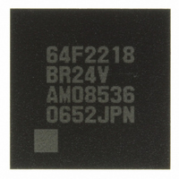
DF2218BR24V Renesas Electronics America, DF2218BR24V Datasheet - Page 24

DF2218BR24V
Manufacturer Part Number
DF2218BR24V
Description
IC H8S/2218 MCU FLASH 112-LFBGA
Manufacturer
Renesas Electronics America
Series
H8® H8S/2200r
Specifications of DF2218BR24V
Core Processor
H8S/2000
Core Size
16-Bit
Speed
24MHz
Connectivity
SCI, SmartCard, USB
Peripherals
DMA, POR, PWM, WDT
Number Of I /o
69
Program Memory Size
128KB (128K x 8)
Program Memory Type
FLASH
Ram Size
12K x 8
Voltage - Supply (vcc/vdd)
2.7 V ~ 3.6 V
Data Converters
A/D 6x10b
Oscillator Type
External
Operating Temperature
-20°C ~ 75°C
Package / Case
112-LFBGA
For Use With
HS0005KCU11H - EMULATOR E10A-USB H8S(X),SH2(A)3DK2218-SS - KIT DEV H8S/2218 WINDOWS SIDESHW3DK2218 - DEV EVAL KIT H8S/2218
Lead Free Status / RoHS Status
Lead free / RoHS Compliant
Eeprom Size
-
Available stocks
Company
Part Number
Manufacturer
Quantity
Price
Company:
Part Number:
DF2218BR24V
Manufacturer:
Renesas Electronics America
Quantity:
10 000
- Current page: 24 of 758
- Download datasheet (5Mb)
2.8
2.9
Section 3 MCU Operating Modes
3.1
3.2
3.3
3.4
Section 4 Exception Handling
4.1
4.2
4.3
4.4
4.5
4.6
4.7
4.8
Section 5 Interrupt Controller
5.1
5.2
5.3
Rev.7.00 Dec. 24, 2008 Page xxii of liv
REJ09B0074-0700
Processing States ............................................................................................................... 64
Usage Notes....................................................................................................................... 66
2.9.1
2.9.2
2.9.3
2.9.4
Operating Mode Selection................................................................................................. 71
Register Descriptions......................................................................................................... 72
3.2.1
3.2.2
Operating Mode Descriptions............................................................................................ 74
3.3.1
3.3.2
3.3.3
3.3.4
3.3.5
Memory Map in Each Operating Mode............................................................................. 77
Exception Handling Types and Priority ............................................................................ 81
Exception Sources and Exception Vector Table................................................................ 81
Reset .................................................................................................................................. 83
4.3.1
4.3.2
4.3.3
4.3.4
Traces ................................................................................................................................ 87
Interrupts ........................................................................................................................... 87
Trap Instruction ................................................................................................................. 88
Stack Status after Exception Handling .............................................................................. 89
Notes on Use of the Stack ................................................................................................. 90
Features ............................................................................................................................. 91
Input/Output Pins .............................................................................................................. 93
Register Descriptions......................................................................................................... 93
5.3.1
5.3.2
Note on TAS Instruction Usage ........................................................................... 66
STM/LTM Instruction Usage ............................................................................... 66
Note on Bit Manipulation Instructions ................................................................. 66
Accessing Registers Containing Write-Only Bits ................................................ 68
Mode Control Register (MDCR).......................................................................... 72
System Control Register (SYSCR) ...................................................................... 72
Mode 4 (Supported Only by the H8S/2218 Group).............................................. 74
Mode 5 (Supported Only by the H8S/2218 Group).............................................. 74
Mode 6 (Supported Only by the H8S/2218 Group).............................................. 75
Mode 7 ................................................................................................................. 75
Pin Functions........................................................................................................ 76
Reset Types .......................................................................................................... 83
Reset Exception Handling .................................................................................... 84
Interrupts after Reset ............................................................................................ 86
State of On-Chip Peripheral Modules after Reset Release ................................... 86
Interrupt Priority Registers A to G, J, K, M
(IPRA to IPRG, IPRJ, IPRK, IPRM) ................................................................... 94
IRQ Enable Register (IER)................................................................................... 95
........................................................................................... 91
.......................................................................................... 81
................................................................................... 71
Related parts for DF2218BR24V
Image
Part Number
Description
Manufacturer
Datasheet
Request
R

Part Number:
Description:
CONN SOCKET 2POS 7.92MM WHITE
Manufacturer:
Hirose Electric Co Ltd
Datasheet:

Part Number:
Description:
CONN SOCKET 4POS 7.92MM WHITE
Manufacturer:
Hirose Electric Co Ltd
Datasheet:

Part Number:
Description:
CONN SOCKET 5POS 7.92MM WHITE
Manufacturer:
Hirose Electric Co Ltd
Datasheet:

Part Number:
Description:
CONN SOCKET 3POS 7.92MM WHITE
Manufacturer:
Hirose Electric Co Ltd
Datasheet:

Part Number:
Description:
CONN SOCKET 5POS 7.92MM WHITE
Manufacturer:
Hirose Electric Co Ltd
Datasheet:

Part Number:
Description:
CONN SOCKET 2POS 7.92MM WHITE
Manufacturer:
Hirose Electric Co Ltd
Datasheet:

Part Number:
Description:
CONN SOCKET 3POS 7.92MM WHITE
Manufacturer:
Hirose Electric Co Ltd
Datasheet:

Part Number:
Description:
CONN SOCKET 4POS 7.92MM WHITE
Manufacturer:
Hirose Electric Co Ltd
Datasheet:

Part Number:
Description:
CONN HEADER 2POS 7.92MM R/A TIN
Manufacturer:
Hirose Electric Co Ltd
Datasheet:

Part Number:
Description:
CONN HEADER 4POS 7.92MM R/A TIN
Manufacturer:
Hirose Electric Co Ltd
Datasheet:

Part Number:
Description:
KIT STARTER FOR M16C/29
Manufacturer:
Renesas Electronics America
Datasheet:

Part Number:
Description:
KIT STARTER FOR R8C/2D
Manufacturer:
Renesas Electronics America
Datasheet:

Part Number:
Description:
R0K33062P STARTER KIT
Manufacturer:
Renesas Electronics America
Datasheet:

Part Number:
Description:
KIT STARTER FOR R8C/23 E8A
Manufacturer:
Renesas Electronics America
Datasheet:

Part Number:
Description:
KIT STARTER FOR R8C/25
Manufacturer:
Renesas Electronics America
Datasheet:


