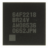
DF2218BR24V Renesas Electronics America, DF2218BR24V Datasheet - Page 585

DF2218BR24V
Manufacturer Part Number
DF2218BR24V
Description
IC H8S/2218 MCU FLASH 112-LFBGA
Manufacturer
Renesas Electronics America
Series
H8® H8S/2200r
Specifications of DF2218BR24V
Core Processor
H8S/2000
Core Size
16-Bit
Speed
24MHz
Connectivity
SCI, SmartCard, USB
Peripherals
DMA, POR, PWM, WDT
Number Of I /o
69
Program Memory Size
128KB (128K x 8)
Program Memory Type
FLASH
Ram Size
12K x 8
Voltage - Supply (vcc/vdd)
2.7 V ~ 3.6 V
Data Converters
A/D 6x10b
Oscillator Type
External
Operating Temperature
-20°C ~ 75°C
Package / Case
112-LFBGA
For Use With
HS0005KCU11H - EMULATOR E10A-USB H8S(X),SH2(A)3DK2218-SS - KIT DEV H8S/2218 WINDOWS SIDESHW3DK2218 - DEV EVAL KIT H8S/2218
Lead Free Status / RoHS Status
Lead free / RoHS Compliant
Eeprom Size
-
Available stocks
Company
Part Number
Manufacturer
Quantity
Price
Company:
Part Number:
DF2218BR24V
Manufacturer:
Renesas Electronics America
Quantity:
10 000
- Current page: 585 of 758
- Download datasheet (5Mb)
14.8.8
14.8.9
EP0 interrupt sources assigned to bits 3 to 0 in UIFR0 must be assigned to the same interrupt
signal (EXIRQx) by setting UISR0. There are no other restrictions on interrupt sources.
pointer that controls the internal module FIFO is updated and correct operation cannot be
guaranteed.
⎯ The manual reset during USB communication operations must not be executed, since the
This USB module uses synchronous reset for some registers. The reset state of these registers
must be cancelled after the clock oscillation stabilization time has passed. At initialization,
reset must be cancelled using the following procedure:
1. Cancel the USB module stop 1: Clear the USBSTOP1 bit in EXMDLSTP to 0.
2. Select the USB operating clock: Write 1 to the UCKS3 to UCKS0 bits in UCTLR.
3. Cancel the USB module stop 2: Clear the MSTPB0 bit in MSTPCRB to 0.
4. Wait for the USB operating clock stabilization: Wait until the CK48READY bit in UIFR3
5. Cancel the USB interface reset state: Clear the UIFRST bit in UCTLR to 0.
6. Cancel the UDC core reset state: Clear the UDCRST bit in UCTLR to 0.
For details, see the flowcharts in section 14.5.1, Initialization and section 14.5.2, USB Cable
Connection/Disconnection.
⎯ The USB registers are not initialized when the watchdog timer (WDT) triggers a power-on
LSI may stop with the state of USD+ and USD- pins maintained.
is set to 1.
reset. Therefore, the USB may not operate properly after a power-on reset is triggered by
the WDT due to CPU runaway or a similar cause. (If a power-on reset is triggered by input
of a power-on reset signal from the RES pin, the USB registers are initialized and there is
no problem.) Consequently, an initialization routine should be used to write the initial
values listed below to the following three registers, thereby ensuring that all the USB
registers are properly initialized, immediately following a reset.
UCTLR = H'03, UIER3 = H'80, UIFR3 = H'00
Reset
EP0 Interrupt Sources Assignment
Rev.7.00 Dec. 24, 2008 Page 529 of 698
REJ09B0074-0700
Related parts for DF2218BR24V
Image
Part Number
Description
Manufacturer
Datasheet
Request
R

Part Number:
Description:
CONN SOCKET 2POS 7.92MM WHITE
Manufacturer:
Hirose Electric Co Ltd
Datasheet:

Part Number:
Description:
CONN SOCKET 4POS 7.92MM WHITE
Manufacturer:
Hirose Electric Co Ltd
Datasheet:

Part Number:
Description:
CONN SOCKET 5POS 7.92MM WHITE
Manufacturer:
Hirose Electric Co Ltd
Datasheet:

Part Number:
Description:
CONN SOCKET 3POS 7.92MM WHITE
Manufacturer:
Hirose Electric Co Ltd
Datasheet:

Part Number:
Description:
CONN SOCKET 5POS 7.92MM WHITE
Manufacturer:
Hirose Electric Co Ltd
Datasheet:

Part Number:
Description:
CONN SOCKET 2POS 7.92MM WHITE
Manufacturer:
Hirose Electric Co Ltd
Datasheet:

Part Number:
Description:
CONN SOCKET 3POS 7.92MM WHITE
Manufacturer:
Hirose Electric Co Ltd
Datasheet:

Part Number:
Description:
CONN SOCKET 4POS 7.92MM WHITE
Manufacturer:
Hirose Electric Co Ltd
Datasheet:

Part Number:
Description:
CONN HEADER 2POS 7.92MM R/A TIN
Manufacturer:
Hirose Electric Co Ltd
Datasheet:

Part Number:
Description:
CONN HEADER 4POS 7.92MM R/A TIN
Manufacturer:
Hirose Electric Co Ltd
Datasheet:

Part Number:
Description:
KIT STARTER FOR M16C/29
Manufacturer:
Renesas Electronics America
Datasheet:

Part Number:
Description:
KIT STARTER FOR R8C/2D
Manufacturer:
Renesas Electronics America
Datasheet:

Part Number:
Description:
R0K33062P STARTER KIT
Manufacturer:
Renesas Electronics America
Datasheet:

Part Number:
Description:
KIT STARTER FOR R8C/23 E8A
Manufacturer:
Renesas Electronics America
Datasheet:

Part Number:
Description:
KIT STARTER FOR R8C/25
Manufacturer:
Renesas Electronics America
Datasheet:


