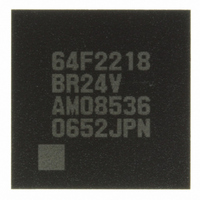
DF2218BR24V Renesas Electronics America, DF2218BR24V Datasheet - Page 36

DF2218BR24V
Manufacturer Part Number
DF2218BR24V
Description
IC H8S/2218 MCU FLASH 112-LFBGA
Manufacturer
Renesas Electronics America
Series
H8® H8S/2200r
Specifications of DF2218BR24V
Core Processor
H8S/2000
Core Size
16-Bit
Speed
24MHz
Connectivity
SCI, SmartCard, USB
Peripherals
DMA, POR, PWM, WDT
Number Of I /o
69
Program Memory Size
128KB (128K x 8)
Program Memory Type
FLASH
Ram Size
12K x 8
Voltage - Supply (vcc/vdd)
2.7 V ~ 3.6 V
Data Converters
A/D 6x10b
Oscillator Type
External
Operating Temperature
-20°C ~ 75°C
Package / Case
112-LFBGA
For Use With
HS0005KCU11H - EMULATOR E10A-USB H8S(X),SH2(A)3DK2218-SS - KIT DEV H8S/2218 WINDOWS SIDESHW3DK2218 - DEV EVAL KIT H8S/2218
Lead Free Status / RoHS Status
Lead free / RoHS Compliant
Eeprom Size
-
Available stocks
Company
Part Number
Manufacturer
Quantity
Price
Company:
Part Number:
DF2218BR24V
Manufacturer:
Renesas Electronics America
Quantity:
10 000
- Current page: 36 of 758
- Download datasheet (5Mb)
20.3 Sleep Mode........................................................................................................................ 618
20.4 Software Standby Mode .................................................................................................... 619
20.5 Hardware Standby Mode................................................................................................... 621
20.6 Module Stop Mode ............................................................................................................ 623
20.7 Watch Mode ...................................................................................................................... 624
20.8 Subsleep Mode .................................................................................................................. 625
20.9 Subactive Mode................................................................................................................. 626
20.10 Direct Transitions .............................................................................................................. 627
20.11 φ Clock Output Disabling Function................................................................................... 627
20.12 Usage Notes....................................................................................................................... 628
Section 21 List of Registers
21.1 Register Addresses (Address Order) ................................................................................. 632
21.2 Register Bits ...................................................................................................................... 640
21.3 Register States in Each Operating Mode ........................................................................... 649
Rev.7.00 Dec. 24, 2008 Page xxxiv of liv
REJ09B0074-0700
20.3.1 Transition to Sleep Mode ..................................................................................... 618
20.3.2 Exiting Sleep Mode .............................................................................................. 618
20.4.1 Transition to Software Standby Mode.................................................................. 619
20.4.2 Clearing Software Standby Mode ........................................................................ 619
20.4.3 Setting Oscillation Stabilization Time after Clearing Software Standby Mode ... 620
20.4.4 Software Standby Mode Application Example .................................................... 620
20.5.1 Transition to Hardware Standby Mode ................................................................ 621
20.5.2 Clearing Hardware Standby Mode ....................................................................... 621
20.5.3 Hardware Standby Mode Timing ......................................................................... 622
20.5.4 Hardware Standby Mode Timings........................................................................ 622
20.7.1 Transition to Watch Mode.................................................................................... 624
20.7.2 Exiting Watch Mode ............................................................................................ 624
20.8.1 Transition to Sleep Mode ..................................................................................... 625
20.8.2 Exiting Subsleep Mode ........................................................................................ 625
20.9.1 Transition to Subactive Mode .............................................................................. 626
20.9.2 Exiting Subactive Mode ....................................................................................... 626
20.10.1 Direct Transitions from High-Speed Mode to Subactive Mode ........................... 627
20.10.2 Direct Transitions from Subactive Mode to High-Speed Mode ........................... 627
20.12.1 I/O Port Status ...................................................................................................... 628
20.12.2 Current Dissipation during Oscillation Stabilization Wait Period........................ 628
20.12.3 Flash Memory Module Stop................................................................................. 628
20.12.4 DMAC Module Stop ............................................................................................ 628
20.12.5 On-Chip Peripheral Module Interrupt .................................................................. 628
20.12.6 Entering Subactive/Watch Mode and DMAC and DTC Module Stop................. 629
20.12.7 Writing to MSTPCR............................................................................................. 629
.............................................................................................. 631
Related parts for DF2218BR24V
Image
Part Number
Description
Manufacturer
Datasheet
Request
R

Part Number:
Description:
CONN SOCKET 2POS 7.92MM WHITE
Manufacturer:
Hirose Electric Co Ltd
Datasheet:

Part Number:
Description:
CONN SOCKET 4POS 7.92MM WHITE
Manufacturer:
Hirose Electric Co Ltd
Datasheet:

Part Number:
Description:
CONN SOCKET 5POS 7.92MM WHITE
Manufacturer:
Hirose Electric Co Ltd
Datasheet:

Part Number:
Description:
CONN SOCKET 3POS 7.92MM WHITE
Manufacturer:
Hirose Electric Co Ltd
Datasheet:

Part Number:
Description:
CONN SOCKET 5POS 7.92MM WHITE
Manufacturer:
Hirose Electric Co Ltd
Datasheet:

Part Number:
Description:
CONN SOCKET 2POS 7.92MM WHITE
Manufacturer:
Hirose Electric Co Ltd
Datasheet:

Part Number:
Description:
CONN SOCKET 3POS 7.92MM WHITE
Manufacturer:
Hirose Electric Co Ltd
Datasheet:

Part Number:
Description:
CONN SOCKET 4POS 7.92MM WHITE
Manufacturer:
Hirose Electric Co Ltd
Datasheet:

Part Number:
Description:
CONN HEADER 2POS 7.92MM R/A TIN
Manufacturer:
Hirose Electric Co Ltd
Datasheet:

Part Number:
Description:
CONN HEADER 4POS 7.92MM R/A TIN
Manufacturer:
Hirose Electric Co Ltd
Datasheet:

Part Number:
Description:
KIT STARTER FOR M16C/29
Manufacturer:
Renesas Electronics America
Datasheet:

Part Number:
Description:
KIT STARTER FOR R8C/2D
Manufacturer:
Renesas Electronics America
Datasheet:

Part Number:
Description:
R0K33062P STARTER KIT
Manufacturer:
Renesas Electronics America
Datasheet:

Part Number:
Description:
KIT STARTER FOR R8C/23 E8A
Manufacturer:
Renesas Electronics America
Datasheet:

Part Number:
Description:
KIT STARTER FOR R8C/25
Manufacturer:
Renesas Electronics America
Datasheet:


