DK-DEV-4SGX230N Altera, DK-DEV-4SGX230N Datasheet - Page 362
DK-DEV-4SGX230N
Manufacturer Part Number
DK-DEV-4SGX230N
Description
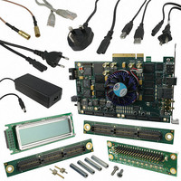
KIT DEVELOPMENT STRATIX IV
Manufacturer
Altera
Series
Stratix® IVr
Type
FPGAr
Datasheets
1.EP4SGX110DF29C3N.pdf
(80 pages)
2.EP4SGX110DF29C3N.pdf
(1154 pages)
3.DK-DEV-4SGX230N.pdf
(2 pages)
4.DK-DEV-4SGX530N.pdf
(57 pages)
Specifications of DK-DEV-4SGX230N
Contents
Development Board, Universal Power Supply, Cables and Software
Silicon Manufacturer
Altera
Core Architecture
FPGA
Core Sub-architecture
Stratix
Silicon Core Number
EP4S
Silicon Family Name
Stratix IV GX
Rohs Compliant
Yes
For Use With/related Products
EP4SGX230K
Lead Free Status / RoHS Status
Lead free / RoHS Compliant
Other names
544-2594
Available stocks
Company
Part Number
Manufacturer
Quantity
Price
Company:

Part Number:
DK-DEV-4SGX230N
Manufacturer:
Altera
Quantity:
135


10–28
Stratix IV Device Handbook Volume 1
1
1
To ensure DCLK and DATA0 are not left floating at the end of configuration, the MAX II
device must drive them either high or low, whichever is convenient on your board.
The DATA[0] pin is available as a user I/O pin after configuration. When you chose the
PS scheme as a default in the Quartus II software, this I/O pin is tri-stated in user
mode and must be driven by the MAX II device. To change this default option in the
Quartus II software, select the Dual-Purpose Pins tab of the Device and Pin Options
dialog box.
The configuration clock (DCLK) speed must be below the specified frequency to ensure
correct configuration. No maximum DCLK period exists, which means you can pause
the configuration by halting DCLK for an indefinite amount of time.
If an error occurs during configuration, the device drives its nSTATUS pin low, resetting
itself internally. The low signal on the nSTATUS pin also alerts the MAX II device that
there is an error. If the Auto-restart configuration after error option (available in the
Quartus II software from the General tab of the Device and Pin Options dialog box)
is turned on, the Stratix IV device releases nSTATUS after a reset time-out period (a
maximum of 500 μs). After nSTATUS is released and pulled high by a pull-up resistor,
the MAX II device can try to reconfigure the target device without needing to pulse
nCONFIG low. If this option is turned off, the MAX II device must generate a
low-to-high transition (with a low pulse of at least 2 μs) on nCONFIG to restart the
configuration process.
If you have enabled the Auto-restart configuration after error option, the nSTATUS pin
transitions from high to low and back again to high when a configuration error is
detected. This appears as a low pulse at the nSTATUS pin with a minimum pulse width
of 10 μs to a maximum pulse width of 500 μs, as defined in the t
The MAX II device can also monitor the CONF_DONE and INIT_DONE pins to ensure
successful configuration. The CONF_DONE pin must be monitored by the MAX II device
to detect errors and determine when programming completes. If all configuration
data is sent, but CONF_DONE or INIT_DONE have not gone high, the MAX II device must
reconfigure the target device.
If you use the optional CLKUSR pin and nCONFIG is pulled low to restart configuration
during device initialization, you must ensure that CLKUSR continues toggling during
the time nSTATUS is low (a maximum of 500 μs).
When the device is in user-mode, you can initiate a reconfiguration by transitioning
the nCONFIG pin low-to-high. The nCONFIG pin must be low for at least 2 μs. When
nCONFIG is pulled low, the device also pulls nSTATUS and CONF_DONE low and all I/O
pins are tri-stated. After nCONFIG returns to a logic high level and nSTATUS is released
by the device, reconfiguration begins.
Chapter 10: Configuration, Design Security, and Remote System Upgrades in Stratix IV Devices
STATUS
April 2011 Altera Corporation
Passive Serial Configuration
specification.
Related parts for DK-DEV-4SGX230N
Image
Part Number
Description
Manufacturer
Datasheet
Request
R

Part Number:
Description:
KIT DEV ARRIA II GX FPGA 2AGX125
Manufacturer:
Altera
Datasheet:

Part Number:
Description:
KIT DEV CYCLONE III LS EP3CLS200
Manufacturer:
Altera
Datasheet:

Part Number:
Description:
KIT DEV STRATIX IV FPGA 4SE530
Manufacturer:
Altera
Datasheet:

Part Number:
Description:
KIT DEV FPGA 2AGX260 W/6.375G TX
Manufacturer:
Altera
Datasheet:

Part Number:
Description:
KIT DEV MAX V 5M570Z
Manufacturer:
Altera
Datasheet:

Part Number:
Description:
KIT DEV STRATIX V FPGA 5SGXEA7
Manufacturer:
Altera
Datasheet:

Part Number:
Description:
KIT DEVELOPMENT STRATIX III
Manufacturer:
Altera
Datasheet:

Part Number:
Description:
KIT DEV ARRIA GX 1AGX60N
Manufacturer:
Altera
Datasheet:
Part Number:
Description:
KIT STARTER CYCLONE IV GX
Manufacturer:
Altera
Datasheet:
Part Number:
Description:
KIT DEVELOPMENT STRATIX IV
Manufacturer:
Altera
Datasheet:

Part Number:
Description:
CPLD, EP610 Family, ECMOS Process, 300 Gates, 16 Macro Cells, 16 Reg., 16 User I/Os, 5V Supply, 35 Speed Grade, 24DIP
Manufacturer:
Altera Corporation
Datasheet:
Part Number:
Description:
CPLD, EP610 Family, ECMOS Process, 300 Gates, 16 Macro Cells, 16 Reg., 16 User I/Os, 5V Supply, 15 Speed Grade, 24DIP
Manufacturer:
Altera Corporation
Datasheet: