DK-DEV-4SGX230N Altera, DK-DEV-4SGX230N Datasheet - Page 835
DK-DEV-4SGX230N
Manufacturer Part Number
DK-DEV-4SGX230N
Description
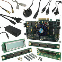
KIT DEVELOPMENT STRATIX IV
Manufacturer
Altera
Series
Stratix® IVr
Type
FPGAr
Datasheets
1.EP4SGX110DF29C3N.pdf
(80 pages)
2.EP4SGX110DF29C3N.pdf
(1154 pages)
3.DK-DEV-4SGX230N.pdf
(2 pages)
4.DK-DEV-4SGX530N.pdf
(57 pages)
Specifications of DK-DEV-4SGX230N
Contents
Development Board, Universal Power Supply, Cables and Software
Silicon Manufacturer
Altera
Core Architecture
FPGA
Core Sub-architecture
Stratix
Silicon Core Number
EP4S
Silicon Family Name
Stratix IV GX
Rohs Compliant
Yes
For Use With/related Products
EP4SGX230K
Lead Free Status / RoHS Status
Lead free / RoHS Compliant
Other names
544-2594
Available stocks
Company
Part Number
Manufacturer
Quantity
Price
Company:

Part Number:
DK-DEV-4SGX230N
Manufacturer:
Altera
Quantity:
135


Chapter 4: Reset Control and Power Down in Stratix IV Devices
PMA Direct Drive Mode Reset Sequences
February 2011 Altera Corporation
As shown in
×4 double-width configuration with CDR in automatic lock mode, follow these reset
steps:
1. After power up, assert pll_powerdown for a minimum period of t
2. Keep the rx_analogreset signal asserted during this time period. After you
3. When the transmitter PLL locks, as indicated by the pll_locked signal going high
4. For the receiver operation, after de-assertion of the busy signal, wait for a
5. Wait for the rx_freqlocked signal from each channel to go high. The
6. In a PMA Direct drive ×4 double-width configuration, when the rx_freqlocked
time between markers 1 and 2).
de-assert the pll_powerdown signal, the transmitter PLL starts locking to the
transmitter input reference clock.
(marker 3), the transmitter is ready to accept parallel data from the FPGA fabric
and transmitting serial data reliably.
minimum of two parallel clock cycles to de-assert the rx_analogreset signals of
each channel. After rx_analogreset is de-asserted, the receiver CDR of each
channel starts locking to the receiver input reference clock.
rx_freqlocked signal of each channel may go high at different times (as indicated
by the slashed pattern at marker 6).
signals of all the channels has gone high (marker 6), from that point onwards, wait
for at least t
this point, all the receivers are ready for transferring valid parallel data into the
FPGA fabric (until this time, Altera recommends that the user logic that processes
this data be under reset).
Figure
LTD_Auto
4–16, for the receiver and transmitter channel in PMA Direct drive
(marker 7) for the receiver parallel clock to become stable. At
Stratix IV Device Handbook Volume 2: Transceivers
pll_powerdown
(the
4–29
Related parts for DK-DEV-4SGX230N
Image
Part Number
Description
Manufacturer
Datasheet
Request
R

Part Number:
Description:
KIT DEV ARRIA II GX FPGA 2AGX125
Manufacturer:
Altera
Datasheet:

Part Number:
Description:
KIT DEV CYCLONE III LS EP3CLS200
Manufacturer:
Altera
Datasheet:

Part Number:
Description:
KIT DEV STRATIX IV FPGA 4SE530
Manufacturer:
Altera
Datasheet:

Part Number:
Description:
KIT DEV FPGA 2AGX260 W/6.375G TX
Manufacturer:
Altera
Datasheet:

Part Number:
Description:
KIT DEV MAX V 5M570Z
Manufacturer:
Altera
Datasheet:

Part Number:
Description:
KIT DEV STRATIX V FPGA 5SGXEA7
Manufacturer:
Altera
Datasheet:

Part Number:
Description:
KIT DEVELOPMENT STRATIX III
Manufacturer:
Altera
Datasheet:

Part Number:
Description:
KIT DEV ARRIA GX 1AGX60N
Manufacturer:
Altera
Datasheet:
Part Number:
Description:
KIT STARTER CYCLONE IV GX
Manufacturer:
Altera
Datasheet:
Part Number:
Description:
KIT DEVELOPMENT STRATIX IV
Manufacturer:
Altera
Datasheet:

Part Number:
Description:
CPLD, EP610 Family, ECMOS Process, 300 Gates, 16 Macro Cells, 16 Reg., 16 User I/Os, 5V Supply, 35 Speed Grade, 24DIP
Manufacturer:
Altera Corporation
Datasheet:
Part Number:
Description:
CPLD, EP610 Family, ECMOS Process, 300 Gates, 16 Macro Cells, 16 Reg., 16 User I/Os, 5V Supply, 15 Speed Grade, 24DIP
Manufacturer:
Altera Corporation
Datasheet: