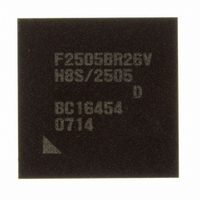
DF2505BR26DV Renesas Electronics America, DF2505BR26DV Datasheet - Page 15

DF2505BR26DV
Manufacturer Part Number
DF2505BR26DV
Description
IC H8S/2505 MCU FLASH 176-LFBGA
Manufacturer
Renesas Electronics America
Series
H8® H8S/2500r
Specifications of DF2505BR26DV
Core Processor
H8S/2000
Core Size
16-Bit
Speed
26MHz
Connectivity
I²C, SCI
Peripherals
POR, PWM, WDT
Number Of I /o
104
Program Memory Size
384KB (384K x 8)
Program Memory Type
FLASH
Ram Size
32K x 8
Voltage - Supply (vcc/vdd)
3 V ~ 5.5 V
Data Converters
A/D 16x10b; D/A 2x8b
Oscillator Type
Internal
Operating Temperature
-40°C ~ 85°C
Package / Case
176-LFBGA
Lead Free Status / RoHS Status
Lead free / RoHS Compliant
Eeprom Size
-
Available stocks
Company
Part Number
Manufacturer
Quantity
Price
Company:
Part Number:
DF2505BR26DV
Manufacturer:
Renesas Electronics America
Quantity:
10 000
- Current page: 15 of 980
- Download datasheet (6Mb)
7.11 Resets and the Bus Controller............................................................................................ 166
Section 8 Data Transfer Controller (DTC) ..........................................................167
8.1
8.2
8.3
8.4
8.5
8.6
8.7
8.8
Section 9 I/O Ports ...............................................................................................193
9.1
7.10.3 Usage Note for External Bus Mastership Release ................................................ 166
Features.............................................................................................................................. 167
Register Descriptions ......................................................................................................... 169
8.2.1
8.2.2
8.2.3
8.2.4
8.2.5
8.2.6
8.2.7
8.2.8
Activation Sources ............................................................................................................. 174
Location of Register Information and DTC Vector Table ................................................. 176
Operation ........................................................................................................................... 180
8.5.1
8.5.2
8.5.3
8.5.4
8.5.5
8.5.6
8.5.7
Procedures for Using DTC................................................................................................. 189
8.6.1
8.6.2
Examples of Use of the DTC ............................................................................................. 190
8.7.1
8.7.2
Usage Notes ....................................................................................................................... 191
8.8.1
8.8.2
8.8.3
Port 1.................................................................................................................................. 199
9.1.1
9.1.2
9.1.3
DTC Mode Register A (MRA) ............................................................................. 170
DTC Mode Register B (MRB).............................................................................. 171
DTC Source Address Register (SAR)................................................................... 172
DTC Destination Address Register (DAR)........................................................... 172
DTC Transfer Count Register A (CRA) ............................................................... 172
DTC Transfer Count Register B (CRB)................................................................ 172
DTC Enable Registers A to G, and I (DTCERA to DTCERG, and DTCERI) ..... 172
DTC Vector Register (DTVECR)......................................................................... 173
Normal Mode........................................................................................................ 181
Repeat Mode ......................................................................................................... 182
Block Transfer Mode ............................................................................................ 183
Chain Transfer ...................................................................................................... 185
Interrupts............................................................................................................... 186
Operation Timing.................................................................................................. 186
Number of DTC Execution States ........................................................................ 187
Activation by Interrupt.......................................................................................... 189
Activation by Software ......................................................................................... 189
Normal Mode........................................................................................................ 190
Software Activation .............................................................................................. 190
Module Stop Mode Setting ................................................................................... 191
On-Chip RAM ...................................................................................................... 191
DTCE Bit Setting.................................................................................................. 191
Port 1 Data Direction Register (P1DDR).............................................................. 199
Port 1 Data Register (P1DR)................................................................................. 200
Port 1 Register (PORT1)....................................................................................... 200
Rev. 6.00 Sep. 24, 2009 Page xiii of xlvi
REJ09B0099-0600
Related parts for DF2505BR26DV
Image
Part Number
Description
Manufacturer
Datasheet
Request
R

Part Number:
Description:
KIT STARTER FOR M16C/29
Manufacturer:
Renesas Electronics America
Datasheet:

Part Number:
Description:
KIT STARTER FOR R8C/2D
Manufacturer:
Renesas Electronics America
Datasheet:

Part Number:
Description:
R0K33062P STARTER KIT
Manufacturer:
Renesas Electronics America
Datasheet:

Part Number:
Description:
KIT STARTER FOR R8C/23 E8A
Manufacturer:
Renesas Electronics America
Datasheet:

Part Number:
Description:
KIT STARTER FOR R8C/25
Manufacturer:
Renesas Electronics America
Datasheet:

Part Number:
Description:
KIT STARTER H8S2456 SHARPE DSPLY
Manufacturer:
Renesas Electronics America
Datasheet:

Part Number:
Description:
KIT STARTER FOR R8C38C
Manufacturer:
Renesas Electronics America
Datasheet:

Part Number:
Description:
KIT STARTER FOR R8C35C
Manufacturer:
Renesas Electronics America
Datasheet:

Part Number:
Description:
KIT STARTER FOR R8CL3AC+LCD APPS
Manufacturer:
Renesas Electronics America
Datasheet:

Part Number:
Description:
KIT STARTER FOR RX610
Manufacturer:
Renesas Electronics America
Datasheet:

Part Number:
Description:
KIT STARTER FOR R32C/118
Manufacturer:
Renesas Electronics America
Datasheet:

Part Number:
Description:
KIT DEV RSK-R8C/26-29
Manufacturer:
Renesas Electronics America
Datasheet:

Part Number:
Description:
KIT STARTER FOR SH7124
Manufacturer:
Renesas Electronics America
Datasheet:

Part Number:
Description:
KIT STARTER FOR H8SX/1622
Manufacturer:
Renesas Electronics America
Datasheet:

Part Number:
Description:
KIT DEV FOR SH7203
Manufacturer:
Renesas Electronics America
Datasheet:


