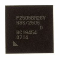
DF2505BR26DV Renesas Electronics America, DF2505BR26DV Datasheet - Page 27

DF2505BR26DV
Manufacturer Part Number
DF2505BR26DV
Description
IC H8S/2505 MCU FLASH 176-LFBGA
Manufacturer
Renesas Electronics America
Series
H8® H8S/2500r
Specifications of DF2505BR26DV
Core Processor
H8S/2000
Core Size
16-Bit
Speed
26MHz
Connectivity
I²C, SCI
Peripherals
POR, PWM, WDT
Number Of I /o
104
Program Memory Size
384KB (384K x 8)
Program Memory Type
FLASH
Ram Size
32K x 8
Voltage - Supply (vcc/vdd)
3 V ~ 5.5 V
Data Converters
A/D 16x10b; D/A 2x8b
Oscillator Type
Internal
Operating Temperature
-40°C ~ 85°C
Package / Case
176-LFBGA
Lead Free Status / RoHS Status
Lead free / RoHS Compliant
Eeprom Size
-
Available stocks
Company
Part Number
Manufacturer
Quantity
Price
Company:
Part Number:
DF2505BR26DV
Manufacturer:
Renesas Electronics America
Quantity:
10 000
- Current page: 27 of 980
- Download datasheet (6Mb)
20.10 Serial Communication Interface Specification for Boot Mode.......................................... 741
20.11 AC Characteristics and Timing in Programmer Mode....................................................... 767
Section 21 Clock Pulse Generator .......................................................................775
21.1 Register Descriptions ......................................................................................................... 776
21.2 System Clock Oscillator..................................................................................................... 780
21.3 PLL Circuit ........................................................................................................................ 784
21.4 Medium-Speed Clock Divider ........................................................................................... 785
21.5 Bus Master Clock Selection Circuit................................................................................... 785
21.6 System Clock with IEBus .................................................................................................. 785
21.7 Subclock Oscillator............................................................................................................ 786
21.8 Subclock Waveform Generation Circuit............................................................................ 787
21.9 Usage Notes ....................................................................................................................... 788
Section 22 Power-Down Modes ..........................................................................791
22.1 Register Descriptions ......................................................................................................... 795
22.2 Medium-Speed Mode......................................................................................................... 799
22.3 Sleep Mode ........................................................................................................................ 800
22.4 Software Standby Mode..................................................................................................... 801
20.9.5 Auto-Erase Mode.................................................................................................. 738
20.9.6 Status-Read Mode................................................................................................. 739
20.9.7 Status Polling ........................................................................................................ 739
20.9.8 Transition Time to Programmer Mode ................................................................. 740
20.9.9 Notes on Programmer Mode................................................................................. 740
21.1.1 System Clock Control Register (SCKCR) ............................................................ 776
21.1.2 Low-Power Control Register (LPWRCR) ............................................................ 777
21.2.1 Connecting Crystal Resonator .............................................................................. 780
21.2.2 External Clock Input............................................................................................. 781
21.2.3 Notes on Switching External Clock ...................................................................... 783
21.7.1 Connecting 32.768-kHz Crystal Resonator........................................................... 786
21.7.2 Handling Pins when Subclock Is Not Used .......................................................... 787
21.9.1 Note on Crystal Resonator .................................................................................... 788
21.9.2 Note on Board Design........................................................................................... 788
22.1.1 Standby Control Register (SBYCR) ..................................................................... 796
22.1.2 Module Stop Control Registers A to C (MSTPCRA to MSTPCRC).................... 797
22.3.1 Transition to Sleep Mode...................................................................................... 800
22.3.2 Clearing Sleep Mode ............................................................................................ 800
22.4.1 Transition to Software Standby Mode .................................................................. 801
22.4.2 Clearing Software Standby Mode ......................................................................... 801
22.4.3 Oscillation Settling Time after Clearing Software Standby Mode........................ 802
Rev. 6.00 Sep. 24, 2009 Page xxv of xlvi
REJ09B0099-0600
Related parts for DF2505BR26DV
Image
Part Number
Description
Manufacturer
Datasheet
Request
R

Part Number:
Description:
KIT STARTER FOR M16C/29
Manufacturer:
Renesas Electronics America
Datasheet:

Part Number:
Description:
KIT STARTER FOR R8C/2D
Manufacturer:
Renesas Electronics America
Datasheet:

Part Number:
Description:
R0K33062P STARTER KIT
Manufacturer:
Renesas Electronics America
Datasheet:

Part Number:
Description:
KIT STARTER FOR R8C/23 E8A
Manufacturer:
Renesas Electronics America
Datasheet:

Part Number:
Description:
KIT STARTER FOR R8C/25
Manufacturer:
Renesas Electronics America
Datasheet:

Part Number:
Description:
KIT STARTER H8S2456 SHARPE DSPLY
Manufacturer:
Renesas Electronics America
Datasheet:

Part Number:
Description:
KIT STARTER FOR R8C38C
Manufacturer:
Renesas Electronics America
Datasheet:

Part Number:
Description:
KIT STARTER FOR R8C35C
Manufacturer:
Renesas Electronics America
Datasheet:

Part Number:
Description:
KIT STARTER FOR R8CL3AC+LCD APPS
Manufacturer:
Renesas Electronics America
Datasheet:

Part Number:
Description:
KIT STARTER FOR RX610
Manufacturer:
Renesas Electronics America
Datasheet:

Part Number:
Description:
KIT STARTER FOR R32C/118
Manufacturer:
Renesas Electronics America
Datasheet:

Part Number:
Description:
KIT DEV RSK-R8C/26-29
Manufacturer:
Renesas Electronics America
Datasheet:

Part Number:
Description:
KIT STARTER FOR SH7124
Manufacturer:
Renesas Electronics America
Datasheet:

Part Number:
Description:
KIT STARTER FOR H8SX/1622
Manufacturer:
Renesas Electronics America
Datasheet:

Part Number:
Description:
KIT DEV FOR SH7203
Manufacturer:
Renesas Electronics America
Datasheet:


