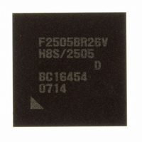
DF2505BR26DV Renesas Electronics America, DF2505BR26DV Datasheet - Page 38

DF2505BR26DV
Manufacturer Part Number
DF2505BR26DV
Description
IC H8S/2505 MCU FLASH 176-LFBGA
Manufacturer
Renesas Electronics America
Series
H8® H8S/2500r
Specifications of DF2505BR26DV
Core Processor
H8S/2000
Core Size
16-Bit
Speed
26MHz
Connectivity
I²C, SCI
Peripherals
POR, PWM, WDT
Number Of I /o
104
Program Memory Size
384KB (384K x 8)
Program Memory Type
FLASH
Ram Size
32K x 8
Voltage - Supply (vcc/vdd)
3 V ~ 5.5 V
Data Converters
A/D 16x10b; D/A 2x8b
Oscillator Type
Internal
Operating Temperature
-40°C ~ 85°C
Package / Case
176-LFBGA
Lead Free Status / RoHS Status
Lead free / RoHS Compliant
Eeprom Size
-
Available stocks
Company
Part Number
Manufacturer
Quantity
Price
Company:
Part Number:
DF2505BR26DV
Manufacturer:
Renesas Electronics America
Quantity:
10 000
- Current page: 38 of 980
- Download datasheet (6Mb)
Section 17 IEBus™ Controller (IEB) [H8S/2552 Group]
Figure 17.1 Block Diagram of IEB ............................................................................................ 540
Figure 17.2 Transfer Signal Format ........................................................................................... 544
Figure 17.3 Bit Configuration of Slave Status (SSR)................................................................. 553
Figure 17.4 Locked Address Configuration ............................................................................... 554
Figure 17.5 IEBus Bit Format (Conceptual Diagram)................................................................ 555
Figure 17.6 Transmission Signal Format and Registers in Data Transfer .................................. 567
Figure 17.7 Relationship between Transmission Signal Format and Registers in IEBus Data
Reception ................................................................................................................ 570
Figure 17.8 Master Transmit Operation Timing......................................................................... 591
Figure 17.9 Slave Reception Operation Timing ......................................................................... 594
Figure 17.10 Error Occurrence in the Broadcast Reception (DEE = 1) ....................................... 595
Figure 17.11 Master Receive Operation Timing .......................................................................... 598
Figure 17.12 Slave Transmit Operation Timing........................................................................... 601
Figure 17.13 Relationships among Transfer Interrupt Sources .................................................... 602
Figure 17.14 Relationships among Receive Interrupt Sources..................................................... 602
Figure 17.15 Error Processing in Transfer ................................................................................... 607
Section 18 Controller Area Network (HCAN) [H8S/2556 Group]
Figure 18.1 HCAN Block Diagram............................................................................................ 610
Figure 18.2 Message Control Register Configuration ................................................................ 634
Figure 18.3 Standard Format ...................................................................................................... 634
Figure 18.4 Extended Format ..................................................................................................... 634
Figure 18.5 Message Data Configuration................................................................................... 636
Figure 18.6 Hardware Reset Flowchart ...................................................................................... 638
Figure 18.7 Software Reset Flowchart ....................................................................................... 639
Figure 18.8 Detailed Description of One Bit.............................................................................. 640
Figure 18.9 Transmission Flowchart .......................................................................................... 644
Figure 18.10 Transmit Message Cancellation Flowchart ............................................................. 646
Figure 18.11 Reception Flowchart ............................................................................................... 648
Figure 18.12 Unread Message Overwrite Flowchart.................................................................... 651
Figure 18.13 HCAN Sleep Mode Flowchart ................................................................................ 652
Figure 18.14 HCAN Halt Mode Flowchart .................................................................................. 653
Figure 18.15 DTC Transfer Flowchart ......................................................................................... 655
Figure 18.16 High-Speed Interface Using PCA82C250............................................................... 656
Figure 18.17 HCAN Transmit Procedure..................................................................................... 660
Section 20 Flash Memory
Figure 20.1 Block Diagram of Flash Memory............................................................................ 667
Figure 20.2 Mode Transition of Flash Memory ......................................................................... 668
Rev. 6.00 Sep. 24, 2009 Page xxxvi of xlvi
REJ09B0099-0600
Related parts for DF2505BR26DV
Image
Part Number
Description
Manufacturer
Datasheet
Request
R

Part Number:
Description:
KIT STARTER FOR M16C/29
Manufacturer:
Renesas Electronics America
Datasheet:

Part Number:
Description:
KIT STARTER FOR R8C/2D
Manufacturer:
Renesas Electronics America
Datasheet:

Part Number:
Description:
R0K33062P STARTER KIT
Manufacturer:
Renesas Electronics America
Datasheet:

Part Number:
Description:
KIT STARTER FOR R8C/23 E8A
Manufacturer:
Renesas Electronics America
Datasheet:

Part Number:
Description:
KIT STARTER FOR R8C/25
Manufacturer:
Renesas Electronics America
Datasheet:

Part Number:
Description:
KIT STARTER H8S2456 SHARPE DSPLY
Manufacturer:
Renesas Electronics America
Datasheet:

Part Number:
Description:
KIT STARTER FOR R8C38C
Manufacturer:
Renesas Electronics America
Datasheet:

Part Number:
Description:
KIT STARTER FOR R8C35C
Manufacturer:
Renesas Electronics America
Datasheet:

Part Number:
Description:
KIT STARTER FOR R8CL3AC+LCD APPS
Manufacturer:
Renesas Electronics America
Datasheet:

Part Number:
Description:
KIT STARTER FOR RX610
Manufacturer:
Renesas Electronics America
Datasheet:

Part Number:
Description:
KIT STARTER FOR R32C/118
Manufacturer:
Renesas Electronics America
Datasheet:

Part Number:
Description:
KIT DEV RSK-R8C/26-29
Manufacturer:
Renesas Electronics America
Datasheet:

Part Number:
Description:
KIT STARTER FOR SH7124
Manufacturer:
Renesas Electronics America
Datasheet:

Part Number:
Description:
KIT STARTER FOR H8SX/1622
Manufacturer:
Renesas Electronics America
Datasheet:

Part Number:
Description:
KIT DEV FOR SH7203
Manufacturer:
Renesas Electronics America
Datasheet:


