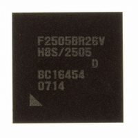
DF2505BR26DV Renesas Electronics America, DF2505BR26DV Datasheet - Page 685

DF2505BR26DV
Manufacturer Part Number
DF2505BR26DV
Description
IC H8S/2505 MCU FLASH 176-LFBGA
Manufacturer
Renesas Electronics America
Series
H8® H8S/2500r
Specifications of DF2505BR26DV
Core Processor
H8S/2000
Core Size
16-Bit
Speed
26MHz
Connectivity
I²C, SCI
Peripherals
POR, PWM, WDT
Number Of I /o
104
Program Memory Size
384KB (384K x 8)
Program Memory Type
FLASH
Ram Size
32K x 8
Voltage - Supply (vcc/vdd)
3 V ~ 5.5 V
Data Converters
A/D 16x10b; D/A 2x8b
Oscillator Type
Internal
Operating Temperature
-40°C ~ 85°C
Package / Case
176-LFBGA
Lead Free Status / RoHS Status
Lead free / RoHS Compliant
Eeprom Size
-
Available stocks
Company
Part Number
Manufacturer
Quantity
Price
Company:
Part Number:
DF2505BR26DV
Manufacturer:
Renesas Electronics America
Quantity:
10 000
- Current page: 685 of 980
- Download datasheet (6Mb)
18.4
18.4.1
The HCAN can be reset by a hardware reset or software reset.
• Hardware Reset
• Software Reset
18.4.2
After a hardware reset, the following initialization processing should be carried out:
1. Clearing of IRR0 bit in the interrupt register (IRR)
2. Bit rate setting
3. Mailbox transmit/receive settings
4. Mailbox (RAM) initialization
5. Message transmission method setting
These initial settings must be made while the HCAN is in bit configuration mode. Configuration
mode is a state in which the GSR3 bit in GSR is set to 1 by a reset. Configuration mode is exited
by clearing the MCR0 bit in MCR to 0; when the MCR0 bit is cleared to 0, the HCAN
automatically clears the GSR3 bit in GSR. There is a delay between clearing the MCR0 bit and
clearing the GSR3 bit because the HCAN needs time to be internally reset, there is a delay
between clearing of the MCR0 bit and GSR3 bit. After the HCAN exits configuration mode, the
power-up sequence begins, and communication with the CAN bus is possible as soon as 11
consecutive recessive bits have been detected.
At power-on reset, or in hardware standby mode, software standby mode, watch mode, or
module stop mode, the HCAN is initialized by automatically setting the MCR reset request bit
(MCR0) in MCR and the reset state bit (GSR3) in GSR. At the same time, all internal
registers, except for message control and message data registers, are initialized by a hardware
reset.
The HCAN can be reset by setting the MCR reset request bit (MCR0) in MCR via software. In
a software reset, the error counters (TEC and REC) are initialized, however other registers are
not. If the MCR0 bit is set while the CAN controller is performing a communication operation
(transmission or reception), the initialization state is not entered until message transfer has
been completed. The reset status bit (GSR3) in GSR is set on completion of initialization.
Operation
Hardware and Software Resets
Initialization after Hardware Reset
Section 18 Controller Area Network (HCAN) [H8S/2556 Group]
Rev. 6.00 Sep. 24, 2009 Page 637 of 928
REJ09B0099-0600
Related parts for DF2505BR26DV
Image
Part Number
Description
Manufacturer
Datasheet
Request
R

Part Number:
Description:
KIT STARTER FOR M16C/29
Manufacturer:
Renesas Electronics America
Datasheet:

Part Number:
Description:
KIT STARTER FOR R8C/2D
Manufacturer:
Renesas Electronics America
Datasheet:

Part Number:
Description:
R0K33062P STARTER KIT
Manufacturer:
Renesas Electronics America
Datasheet:

Part Number:
Description:
KIT STARTER FOR R8C/23 E8A
Manufacturer:
Renesas Electronics America
Datasheet:

Part Number:
Description:
KIT STARTER FOR R8C/25
Manufacturer:
Renesas Electronics America
Datasheet:

Part Number:
Description:
KIT STARTER H8S2456 SHARPE DSPLY
Manufacturer:
Renesas Electronics America
Datasheet:

Part Number:
Description:
KIT STARTER FOR R8C38C
Manufacturer:
Renesas Electronics America
Datasheet:

Part Number:
Description:
KIT STARTER FOR R8C35C
Manufacturer:
Renesas Electronics America
Datasheet:

Part Number:
Description:
KIT STARTER FOR R8CL3AC+LCD APPS
Manufacturer:
Renesas Electronics America
Datasheet:

Part Number:
Description:
KIT STARTER FOR RX610
Manufacturer:
Renesas Electronics America
Datasheet:

Part Number:
Description:
KIT STARTER FOR R32C/118
Manufacturer:
Renesas Electronics America
Datasheet:

Part Number:
Description:
KIT DEV RSK-R8C/26-29
Manufacturer:
Renesas Electronics America
Datasheet:

Part Number:
Description:
KIT STARTER FOR SH7124
Manufacturer:
Renesas Electronics America
Datasheet:

Part Number:
Description:
KIT STARTER FOR H8SX/1622
Manufacturer:
Renesas Electronics America
Datasheet:

Part Number:
Description:
KIT DEV FOR SH7203
Manufacturer:
Renesas Electronics America
Datasheet:


