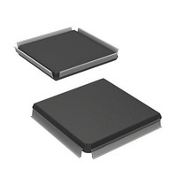
HD6417751RF240V Renesas Electronics America, HD6417751RF240V Datasheet - Page 623

HD6417751RF240V
Manufacturer Part Number
HD6417751RF240V
Description
MPU 1.5/3.3V 0K PB-FREE 256-QFP
Manufacturer
Renesas Electronics America
Series
SuperH® SH7750r
Datasheet
1.D6417751RBP200DV.pdf
(1226 pages)
Specifications of HD6417751RF240V
Core Processor
SH-4
Core Size
32-Bit
Speed
240MHz
Connectivity
EBI/EMI, FIFO, SCI, SmartCard
Peripherals
DMA, POR, WDT
Number Of I /o
39
Program Memory Type
ROMless
Ram Size
48K x 8
Voltage - Supply (vcc/vdd)
1.4 V ~ 1.6 V
Oscillator Type
External
Operating Temperature
-20°C ~ 75°C
Package / Case
256-QFP Exposed Pad, 256-eQFP, 256-HQFP
Lead Free Status / RoHS Status
Lead free / RoHS Compliant
Eeprom Size
-
Program Memory Size
-
Data Converters
-
Available stocks
Company
Part Number
Manufacturer
Quantity
Price
Company:
Part Number:
HD6417751RF240V
Manufacturer:
Renesas Electronics America
Quantity:
10 000
- Current page: 623 of 1226
- Download datasheet (7Mb)
Notes: SCI/SCIF burst transfer setting is prohibited.
To output a transfer request from an on-chip peripheral module, set the DMA transfer request
enable bit for that module and output a transfer request signal.
For details, see sections 12, Timer Unit (TMU), 15, Serial Communication Interface (SCI), and
16, Serial Communication Interface with FIFO (SCIF).
When a DMA transfer corresponding to a transfer request signal from an on-chip peripheral
module shown in table 14.5 is carried out, the signal is discontinued automatically. This occurs
every transfer in cycle steal mode, and in the last transfer in burst mode.
14.3.3
If the DMAC receives simultaneous transfer requests on two or more channels, it selects a channel
according to a predetermined priority system, either in a fixed mode or round robin mode. The
mode is selected with priority bits PR1 and PR0 in the DMA operation register (DMAOR).
Fixed Mode: In this mode, the relative channel priorities remain fixed. The following priority
orders are available in fixed mode:
• CH0 > CH1 > CH2 > CH3
• CH0 > CH2 > CH3 > CH1
• CH2 > CH0 > CH1 > CH3
The priority order is selected with bits PR1 and PR0 in DMAOR.
Round Robin Mode: In round robin mode, each time the transfer of one transfer unit (byte, word,
longword, quadword, or 32 bytes) ends on a given channel, that channel is assigned the lowest
priority level. This is illustrated in figure 14.3. The order of priority in round robin mode
immediately after a reset is CH0 > CH1 > CH2 > CH3.
Note: In round robin mode, if no transfer request is accepted for any channel during DMA
If input capture interrupt acceptance is set for multiple channels and DE =1 for each
channel, processing will be executed on the highest-priority channel in response to a single
input capture interrupt.
A DMA transfer request by means of an input capture interrupt can be canceled by setting
TCR2.ICPE1 = 0 and TCR2.ICPE0 = 0 in the TMU.
*
transfer, the priority order becomes CH0 > CH1 > CH2 > CH3.
Channel Priorities
External memory or memory-mapped external device
14. Direct Memory Access Controller (DMAC)
Rev.4.00 Oct. 10, 2008 Page 523 of 1122
REJ09B0370-0400
Related parts for HD6417751RF240V
Image
Part Number
Description
Manufacturer
Datasheet
Request
R

Part Number:
Description:
KIT STARTER FOR M16C/29
Manufacturer:
Renesas Electronics America
Datasheet:

Part Number:
Description:
KIT STARTER FOR R8C/2D
Manufacturer:
Renesas Electronics America
Datasheet:

Part Number:
Description:
R0K33062P STARTER KIT
Manufacturer:
Renesas Electronics America
Datasheet:

Part Number:
Description:
KIT STARTER FOR R8C/23 E8A
Manufacturer:
Renesas Electronics America
Datasheet:

Part Number:
Description:
KIT STARTER FOR R8C/25
Manufacturer:
Renesas Electronics America
Datasheet:

Part Number:
Description:
KIT STARTER H8S2456 SHARPE DSPLY
Manufacturer:
Renesas Electronics America
Datasheet:

Part Number:
Description:
KIT STARTER FOR R8C38C
Manufacturer:
Renesas Electronics America
Datasheet:

Part Number:
Description:
KIT STARTER FOR R8C35C
Manufacturer:
Renesas Electronics America
Datasheet:

Part Number:
Description:
KIT STARTER FOR R8CL3AC+LCD APPS
Manufacturer:
Renesas Electronics America
Datasheet:

Part Number:
Description:
KIT STARTER FOR RX610
Manufacturer:
Renesas Electronics America
Datasheet:

Part Number:
Description:
KIT STARTER FOR R32C/118
Manufacturer:
Renesas Electronics America
Datasheet:

Part Number:
Description:
KIT DEV RSK-R8C/26-29
Manufacturer:
Renesas Electronics America
Datasheet:

Part Number:
Description:
KIT STARTER FOR SH7124
Manufacturer:
Renesas Electronics America
Datasheet:

Part Number:
Description:
KIT STARTER FOR H8SX/1622
Manufacturer:
Renesas Electronics America
Datasheet:

Part Number:
Description:
KIT DEV FOR SH7203
Manufacturer:
Renesas Electronics America
Datasheet:


