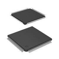
DF2398TE20 Renesas Electronics America, DF2398TE20 Datasheet - Page 367

DF2398TE20
Manufacturer Part Number
DF2398TE20
Description
IC H8S MCU FLASH 256K 120TQFP
Manufacturer
Renesas Electronics America
Series
H8® H8S/2300r
Specifications of DF2398TE20
Core Processor
H8S/2000
Core Size
16-Bit
Speed
20MHz
Connectivity
SCI, SmartCard
Peripherals
DMA, POR, PWM, WDT
Number Of I /o
87
Program Memory Size
256KB (256K x 8)
Program Memory Type
FLASH
Ram Size
8K x 8
Voltage - Supply (vcc/vdd)
4.5 V ~ 5.5 V
Data Converters
A/D 8x10b; D/A 2x8b
Oscillator Type
Internal
Operating Temperature
-20°C ~ 75°C
Package / Case
120-TQFP, 120-VQFP
Lead Free Status / RoHS Status
Contains lead / RoHS non-compliant
Eeprom Size
-
Other names
HD64F2398TE20
HD64F2398TE20
HD64F2398TE20
Available stocks
Company
Part Number
Manufacturer
Quantity
Price
Company:
Part Number:
DF2398TE20V
Manufacturer:
Renesas Electronics America
Quantity:
10 000
- Current page: 367 of 1049
- Download datasheet (5Mb)
10.1
The H8S/2357 Group has an on-chip 16-bit timer pulse unit (TPU) that comprises six 16-bit timer channels.
10.1.1
Maximum 16-pulse input/output
Selection of 8 counter input clocks for each channel
The following operations can be set for each channel:
Buffer operation settable for channels 0 and 3
Phase counting mode settable independently for each of channels 1, 2, 4, and 5
Cascaded operation
Fast access via internal 16-bit bus
26 interrupt sources
Automatic transfer of register data
Programmable pulse generator (PPG) output trigger can be generated
A total of 16 timer general registers (TGRs) are provided (four each for channels 0 and 3, and two each for
TGRC and TGRD for channels 0 and 3 can also be used as buffer registers
Waveform output at compare match: Selection of 0, 1, or toggle output
Input capture function: Selection of rising edge, falling edge, or both edge detection
Counter clear operation: Counter clearing possible by compare match or input capture
Synchronous operation: Multiple timer counters (TCNT) can be written to simultaneously. Simultaneous clearing
PWM mode: Any PWM output duty can be set. Maximum of 15-phase PWM output possible by combination with
Input capture register double-buffering possible
Automatic rewriting of output compare register possible
Two-phase encoder pulse up/down-count possible
Channel 2 (channel 5) input clock operates as 32-bit counter by setting channel 1 (channel 4) overflow/underflow
Fast access is possible via a 16-bit bus interface
For channels 0 and 3, four compare match/input capture dual-function interrupts and one overflow interrupt can be
For channels 1, 2, 4, and 5, two compare match/input capture dual-function interrupts, one overflow interrupt, and
Block transfer, 1-word data transfer, and 1-byte data transfer possible by data transfer controller (DTC) or DMA
Channel 0 to 3 compare match/input capture signals can be used as PPG output trigger
channels 1, 2, 4, and 5), each of which can be set independently as an output compare/input capture register
by compare match and input capture possible. Register simultaneous input/output possible by counter synchronous
operation
synchronous operation
requested independently
one underflow interrupt can be requested independently
controller (DMAC) activation
Overview
Features
Section 10 16-Bit Timer Pulse Unit (TPU)
Rev.6.00 Oct.28.2004 page 337 of 1016
REJ09B0138-0600H
Related parts for DF2398TE20
Image
Part Number
Description
Manufacturer
Datasheet
Request
R

Part Number:
Description:
CONN PLUG 12POS DUAL 0.5MM SMD
Manufacturer:
Hirose Electric Co Ltd
Datasheet:

Part Number:
Description:
CONN PLUG 18POS DUAL 0.5MM SMD
Manufacturer:
Hirose Electric Co Ltd
Datasheet:

Part Number:
Description:
CONN PLUG 14POS DUAL 0.5MM SMD
Manufacturer:
Hirose Electric Co Ltd
Datasheet:

Part Number:
Description:
CONN RECEPT 20POS DUAL 0.5MM SMD
Manufacturer:
Hirose Electric Co Ltd
Datasheet:

Part Number:
Description:
CONN PLUG 16POS DUAL 0.5MM SMD
Manufacturer:
Hirose Electric Co Ltd
Datasheet:

Part Number:
Description:
CONN RECEPT 16POS DUAL 0.5MM SMD
Manufacturer:
Hirose Electric Co Ltd
Datasheet:

Part Number:
Description:
CONN PLUG 20POS DUAL 0.5MM SMD
Manufacturer:
Hirose Electric Co Ltd
Datasheet:

Part Number:
Description:
CONN PLUG 30POS DUAL 0.5MM SMD
Manufacturer:
Hirose Electric Co Ltd
Datasheet:

Part Number:
Description:
CONN RECEPT 30POS DUAL 0.5MM SMD
Manufacturer:
Hirose Electric Co Ltd
Datasheet:

Part Number:
Description:
CONN PLUG 40POS DUAL 0.5MM SMD
Manufacturer:
Hirose Electric Co Ltd
Datasheet:

Part Number:
Description:
KIT STARTER FOR M16C/29
Manufacturer:
Renesas Electronics America
Datasheet:

Part Number:
Description:
KIT STARTER FOR R8C/2D
Manufacturer:
Renesas Electronics America
Datasheet:

Part Number:
Description:
R0K33062P STARTER KIT
Manufacturer:
Renesas Electronics America
Datasheet:

Part Number:
Description:
KIT STARTER FOR R8C/23 E8A
Manufacturer:
Renesas Electronics America
Datasheet:

Part Number:
Description:
KIT STARTER FOR R8C/25
Manufacturer:
Renesas Electronics America
Datasheet:


