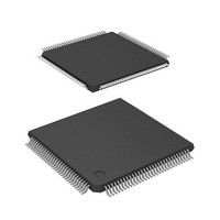
DF2398TE20 Renesas Electronics America, DF2398TE20 Datasheet - Page 78

DF2398TE20
Manufacturer Part Number
DF2398TE20
Description
IC H8S MCU FLASH 256K 120TQFP
Manufacturer
Renesas Electronics America
Series
H8® H8S/2300r
Specifications of DF2398TE20
Core Processor
H8S/2000
Core Size
16-Bit
Speed
20MHz
Connectivity
SCI, SmartCard
Peripherals
DMA, POR, PWM, WDT
Number Of I /o
87
Program Memory Size
256KB (256K x 8)
Program Memory Type
FLASH
Ram Size
8K x 8
Voltage - Supply (vcc/vdd)
4.5 V ~ 5.5 V
Data Converters
A/D 8x10b; D/A 2x8b
Oscillator Type
Internal
Operating Temperature
-20°C ~ 75°C
Package / Case
120-TQFP, 120-VQFP
Lead Free Status / RoHS Status
Contains lead / RoHS non-compliant
Eeprom Size
-
Other names
HD64F2398TE20
HD64F2398TE20
HD64F2398TE20
Available stocks
Company
Part Number
Manufacturer
Quantity
Price
Company:
Part Number:
DF2398TE20V
Manufacturer:
Renesas Electronics America
Quantity:
10 000
- Current page: 78 of 1049
- Download datasheet (5Mb)
2.8.2
When the RES input goes low all current processing stops and the CPU enters the reset state. The CPU enters the power-
on reset state when the NMI pin is high, or the manual reset* state when the NMI pin is low. All interrupts are masked in
the reset state. Reset exception handling starts when the RES signal changes from low to high.
The reset state can also be entered by a watchdog timer overflow. For details, refer to section 13, Watchdog Timer.
Note: * Manual reset is only supported in the H8S/2357 ZTAT.
2.8.3
The exception-handling state is a transient state that occurs when the CPU alters the normal processing flow due to a reset,
interrupt, or trap instruction. The CPU fetches a start address (vector) from the exception vector table and branches to that
address.
(1) Types of Exception Handling and Their Priority
Exception handling is performed for traces, resets, interrupts, and trap instructions. Table 2-7 indicates the types of
exception handling and their priority. Trap instruction exception handling is always accepted, in the program execution
state.
Exception handling and the stack structure depend on the interrupt control mode set in SYSCR.
Rev.6.00 Oct.28.2004 page 48 of 1016
REJ09B0138-0600H
Reset State
Exception-Handling State
Notes: 1.
RES = high
Exception-handling state
2.
Bus-released state
From any state except hardware standby mode, a transition to the reset state occurs whenever RES
goes low. A transition can also be made to the reset state when the watchdog timer overflows.
From any state, a transition to hardware standby mode occurs when STBY goes low.
Reset state
End of bus
request
End of
exception
handling
*1
Figure 2-12 State Transitions
Bus
request
STBY = high, RES = low
External interrupt
Request for
exception
handling
Program execution
End of bus request
Bus request
state
Interrupt
request
SLEEP
instruction
with
SSBY = 1
Hardware standby mode
SLEEP
instruction
with
SSBY = 0
Software standby mode
Power-down state
Sleep mode
*2
Related parts for DF2398TE20
Image
Part Number
Description
Manufacturer
Datasheet
Request
R

Part Number:
Description:
CONN PLUG 12POS DUAL 0.5MM SMD
Manufacturer:
Hirose Electric Co Ltd
Datasheet:

Part Number:
Description:
CONN PLUG 18POS DUAL 0.5MM SMD
Manufacturer:
Hirose Electric Co Ltd
Datasheet:

Part Number:
Description:
CONN PLUG 14POS DUAL 0.5MM SMD
Manufacturer:
Hirose Electric Co Ltd
Datasheet:

Part Number:
Description:
CONN RECEPT 20POS DUAL 0.5MM SMD
Manufacturer:
Hirose Electric Co Ltd
Datasheet:

Part Number:
Description:
CONN PLUG 16POS DUAL 0.5MM SMD
Manufacturer:
Hirose Electric Co Ltd
Datasheet:

Part Number:
Description:
CONN RECEPT 16POS DUAL 0.5MM SMD
Manufacturer:
Hirose Electric Co Ltd
Datasheet:

Part Number:
Description:
CONN PLUG 20POS DUAL 0.5MM SMD
Manufacturer:
Hirose Electric Co Ltd
Datasheet:

Part Number:
Description:
CONN PLUG 30POS DUAL 0.5MM SMD
Manufacturer:
Hirose Electric Co Ltd
Datasheet:

Part Number:
Description:
CONN RECEPT 30POS DUAL 0.5MM SMD
Manufacturer:
Hirose Electric Co Ltd
Datasheet:

Part Number:
Description:
CONN PLUG 40POS DUAL 0.5MM SMD
Manufacturer:
Hirose Electric Co Ltd
Datasheet:

Part Number:
Description:
KIT STARTER FOR M16C/29
Manufacturer:
Renesas Electronics America
Datasheet:

Part Number:
Description:
KIT STARTER FOR R8C/2D
Manufacturer:
Renesas Electronics America
Datasheet:

Part Number:
Description:
R0K33062P STARTER KIT
Manufacturer:
Renesas Electronics America
Datasheet:

Part Number:
Description:
KIT STARTER FOR R8C/23 E8A
Manufacturer:
Renesas Electronics America
Datasheet:

Part Number:
Description:
KIT STARTER FOR R8C/25
Manufacturer:
Renesas Electronics America
Datasheet:


