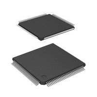
DF2398TE20 Renesas Electronics America, DF2398TE20 Datasheet - Page 757

DF2398TE20
Manufacturer Part Number
DF2398TE20
Description
IC H8S MCU FLASH 256K 120TQFP
Manufacturer
Renesas Electronics America
Series
H8® H8S/2300r
Specifications of DF2398TE20
Core Processor
H8S/2000
Core Size
16-Bit
Speed
20MHz
Connectivity
SCI, SmartCard
Peripherals
DMA, POR, PWM, WDT
Number Of I /o
87
Program Memory Size
256KB (256K x 8)
Program Memory Type
FLASH
Ram Size
8K x 8
Voltage - Supply (vcc/vdd)
4.5 V ~ 5.5 V
Data Converters
A/D 8x10b; D/A 2x8b
Oscillator Type
Internal
Operating Temperature
-20°C ~ 75°C
Package / Case
120-TQFP, 120-VQFP
Lead Free Status / RoHS Status
Contains lead / RoHS non-compliant
Eeprom Size
-
Other names
HD64F2398TE20
HD64F2398TE20
HD64F2398TE20
Available stocks
Company
Part Number
Manufacturer
Quantity
Price
Company:
Part Number:
DF2398TE20V
Manufacturer:
Renesas Electronics America
Quantity:
10 000
- Current page: 757 of 1049
- Download datasheet (5Mb)
22.4
The F-ZTAT and masked ROM versions satisfy electrical characteristics described in this manual. However, actual
electrical characteristics values, operation margins, and noise margins depend on differences in manufacturing processes,
on-chip ROM, or layout patterns.
If the system is evaluated using the F-ZTAT version, perform the same evaluation test of the system using the masked
ROM version when switching to the masked ROM version.
22.5
The H8S/2398 F-ZTAT have a voltage step down circuit that automatically lowers the power supply voltage, inside the
microcomputer, to an adequate level. A capacitor (one 0.47- F capacitor or two 0.47- F capacitors connected in parallel)
should be connected between the V
voltage. Figure 22-64 shows how to connect the capacitor. Do not connect the V
could permanently damage the LSI. (Connect the V
5. The maximum writing count (N) must be set to the maximum writing time (t
6. Wait time (z) after setting of bit E and the maximum erasing count (N) have the following relationship to the
Notes on Use
Usage Note (Internal Voltage Step Down for the H8S/2398 F-ZTAT)
set value (z). Wait time (z) must be switched after setting of bit P according to writing count (n).
Writing count n
1
7
[In additional writing]
Writing count n
1
maximum erasing time (t
t
E
(max) = wait time (z) after setting of bit E maximum erasing count (N)
n
n
n
6
1000
6
An external capacitor to
stabilize the internal voltage
One 0.47- F capacitor
or two 0.47- F capacitors
connected in parallel
Do not connect the V
If connected, the LSI may be permanently damaged.
Connect the V
Use a multilayer ceramic capacitor (one 0.47- F capacitor or two 0.
47- F capacitors connected in parallel) for this circuit, and place it/them
near the V
z = 30 s
z = 200 s
z = 10 s
Figure 22-64 V
CL
E
CL
(max)).
pin (a pin for internal voltage step down circuit) and V
pin.
CC
power-supply to the other V
CC
power-supply to the V
CC
CL
power-supply to the V
Capacitor Connection Method
V
V
CL
SS
CC
CL
pin in the usual way.
pin.
CC
pin, in the usual way.)
CC
Rev.6.00 Oct.28.2004 page 727 of 1016
power-supply to the V
P
(max)) or less according the actual
SS
pin to stabilize the internal
REJ09B0138-0600H
CL
pin. Doing so
Related parts for DF2398TE20
Image
Part Number
Description
Manufacturer
Datasheet
Request
R

Part Number:
Description:
CONN PLUG 12POS DUAL 0.5MM SMD
Manufacturer:
Hirose Electric Co Ltd
Datasheet:

Part Number:
Description:
CONN PLUG 18POS DUAL 0.5MM SMD
Manufacturer:
Hirose Electric Co Ltd
Datasheet:

Part Number:
Description:
CONN PLUG 14POS DUAL 0.5MM SMD
Manufacturer:
Hirose Electric Co Ltd
Datasheet:

Part Number:
Description:
CONN RECEPT 20POS DUAL 0.5MM SMD
Manufacturer:
Hirose Electric Co Ltd
Datasheet:

Part Number:
Description:
CONN PLUG 16POS DUAL 0.5MM SMD
Manufacturer:
Hirose Electric Co Ltd
Datasheet:

Part Number:
Description:
CONN RECEPT 16POS DUAL 0.5MM SMD
Manufacturer:
Hirose Electric Co Ltd
Datasheet:

Part Number:
Description:
CONN PLUG 20POS DUAL 0.5MM SMD
Manufacturer:
Hirose Electric Co Ltd
Datasheet:

Part Number:
Description:
CONN PLUG 30POS DUAL 0.5MM SMD
Manufacturer:
Hirose Electric Co Ltd
Datasheet:

Part Number:
Description:
CONN RECEPT 30POS DUAL 0.5MM SMD
Manufacturer:
Hirose Electric Co Ltd
Datasheet:

Part Number:
Description:
CONN PLUG 40POS DUAL 0.5MM SMD
Manufacturer:
Hirose Electric Co Ltd
Datasheet:

Part Number:
Description:
KIT STARTER FOR M16C/29
Manufacturer:
Renesas Electronics America
Datasheet:

Part Number:
Description:
KIT STARTER FOR R8C/2D
Manufacturer:
Renesas Electronics America
Datasheet:

Part Number:
Description:
R0K33062P STARTER KIT
Manufacturer:
Renesas Electronics America
Datasheet:

Part Number:
Description:
KIT STARTER FOR R8C/23 E8A
Manufacturer:
Renesas Electronics America
Datasheet:

Part Number:
Description:
KIT STARTER FOR R8C/25
Manufacturer:
Renesas Electronics America
Datasheet:


