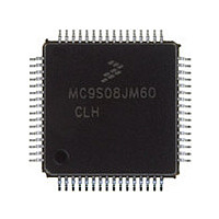
MC9S08JM60CLH Freescale, MC9S08JM60CLH Datasheet - Page 299

MC9S08JM60CLH
Manufacturer Part Number
MC9S08JM60CLH
Description
Manufacturer
Freescale
Datasheet
1.MC9S08JM60CLH.pdf
(388 pages)
Specifications of MC9S08JM60CLH
Cpu Family
HCS08
Device Core Size
8b
Frequency (max)
24MHz
Interface Type
SCI/SPI
Total Internal Ram Size
4KB
# I/os (max)
51
Number Of Timers - General Purpose
8
Operating Supply Voltage (typ)
3.3/5V
Operating Supply Voltage (max)
5.5V
Operating Supply Voltage (min)
2.7V
On-chip Adc
12-chx12-bit
Instruction Set Architecture
CISC
Operating Temp Range
-40C to 85C
Operating Temperature Classification
Industrial
Mounting
Surface Mount
Pin Count
64
Package Type
LQFP
Program Memory Type
Flash
Program Memory Size
60KB
Lead Free Status / RoHS Status
Compliant
Available stocks
Company
Part Number
Manufacturer
Quantity
Price
Company:
Part Number:
MC9S08JM60CLH
Manufacturer:
Freescale Semiconductor
Quantity:
10 000
Part Number:
MC9S08JM60CLH
Manufacturer:
FREESCALE
Quantity:
20 000
Company:
Part Number:
MC9S08JM60CLHE
Manufacturer:
AZBIL
Quantity:
1 000
- Current page: 299 of 388
- Download datasheet (5Mb)
17.1.6
Figure 17-2
Freescale Semiconductor
Mode
Stop3
Wait
24-MHz Clock (bus clk)
48-MHz Reference Clock
Block Diagram
is a block diagram of the USB module.
The USB module is optionally available in stop3.
A reduced current consumption mode may be required for USB suspend mode per USB Specification Rev. 2.0,
and stop3 mode is useful for achieving lower current consumption for the MCU and hence the overall USB
device. Before entering stop3 via firmware, the user must ensure that the device settings are configured for
stop3 to achieve USB suspend current consumption targets.
The USB module is notified about entering suspend mode when the SLEEPF flag is set; this occurs after the
USB bus is idle for 3 ms. The device USB suspend mode current consumption level requirements are defined
by the USB Specification Rev. 2.0 (500 μA for low-power and 2.5 mA for high-power with remote-wakeup
enabled).
If USBRESMEN in USBCTL0 is set, and a K-state (resume signaling) is detected on the USB bus, the LPRESF
bit in USBCTL0 will be set. This triggers an asynchronous interrupt that will wakeup the MCU from stop3 mode
and enable clocks to the USB module. The USBRESMEN bit must then be cleared immediately after stop3
recovery to clear the LPRESF flag bit.
USB module is operational.
IRQ
USB CONTROLLER
Table 17-2. Operating Modes (continued)
Figure 17-2. USB Module Block Diagram
MC9S08JM60 Series Data Sheet, Rev. 3
USB RAM
256 bytes
Description
Serial Interface Engine
(SIE)
Initiator
Target
BVCI
BVCI
Protocol and Rate
Match
Universal Serial Bus Device Controller (S08USBV1)
Logic
Logic
RX
TX
Enable
USBDP Pullup
XCVR
VREG
V
USBDN
USBDP
USB33
299
Related parts for MC9S08JM60CLH
Image
Part Number
Description
Manufacturer
Datasheet
Request
R

Part Number:
Description:
TOWER ELEVATOR BOARDS HARDWARE
Manufacturer:
Freescale Semiconductor
Datasheet:

Part Number:
Description:
TOWER SERIAL I/O HARDWARE
Manufacturer:
Freescale Semiconductor
Datasheet:

Part Number:
Description:
LCD MODULE FOR TWR SYSTEM
Manufacturer:
Freescale Semiconductor
Datasheet:

Part Number:
Description:
DAUGHTER LCD WVGA I.MX51
Manufacturer:
Freescale Semiconductor
Datasheet:

Part Number:
Description:
TOWER SYSTEM BOARD MPC5125
Manufacturer:
Freescale Semiconductor
Datasheet:

Part Number:
Description:
KIT EVALUATION I.MX51
Manufacturer:
Freescale Semiconductor
Datasheet:

Part Number:
Description:
KIT DEVELOPMENT WINCE IMX25
Manufacturer:
Freescale Semiconductor
Datasheet:

Part Number:
Description:
TOWER SYSTEM KIT MPC5125
Manufacturer:
Freescale Semiconductor
Datasheet:

Part Number:
Description:
TOWER SYSTEM BOARD K40X256
Manufacturer:
Freescale Semiconductor
Datasheet:

Part Number:
Description:
TOWER SYSTEM KIT K40X256
Manufacturer:
Freescale Semiconductor
Datasheet:

Part Number:
Description:
Microcontrollers (MCU) MX28 PLATFORM DEV KIT
Manufacturer:
Freescale Semiconductor
Datasheet:

Part Number:
Description:
MCU, MPU & DSP Development Tools IAR KickStart Kit for Kinetis K60
Manufacturer:
Freescale Semiconductor
Datasheet:

Part Number:
Description:
24BIT HDMI MX535/08
Manufacturer:
Freescale Semiconductor
Datasheet:
Part Number:
Description:
Manufacturer:
Freescale Semiconductor, Inc
Datasheet:
Part Number:
Description:
Manufacturer:
Freescale Semiconductor, Inc
Datasheet:


