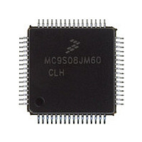
MC9S08JM60CLH Freescale, MC9S08JM60CLH Datasheet - Page 339

MC9S08JM60CLH
Manufacturer Part Number
MC9S08JM60CLH
Description
Manufacturer
Freescale
Datasheet
1.MC9S08JM60CLH.pdf
(388 pages)
Specifications of MC9S08JM60CLH
Cpu Family
HCS08
Device Core Size
8b
Frequency (max)
24MHz
Interface Type
SCI/SPI
Total Internal Ram Size
4KB
# I/os (max)
51
Number Of Timers - General Purpose
8
Operating Supply Voltage (typ)
3.3/5V
Operating Supply Voltage (max)
5.5V
Operating Supply Voltage (min)
2.7V
On-chip Adc
12-chx12-bit
Instruction Set Architecture
CISC
Operating Temp Range
-40C to 85C
Operating Temperature Classification
Industrial
Mounting
Surface Mount
Pin Count
64
Package Type
LQFP
Program Memory Type
Flash
Program Memory Size
60KB
Lead Free Status / RoHS Status
Compliant
Available stocks
Company
Part Number
Manufacturer
Quantity
Price
Company:
Part Number:
MC9S08JM60CLH
Manufacturer:
Freescale Semiconductor
Quantity:
10 000
Part Number:
MC9S08JM60CLH
Manufacturer:
FREESCALE
Quantity:
20 000
Company:
Part Number:
MC9S08JM60CLHE
Manufacturer:
AZBIL
Quantity:
1 000
- Current page: 339 of 388
- Download datasheet (5Mb)
Development Support
A force-type breakpoint waits for the current instruction to finish and then acts upon the breakpoint
request. The usual action in response to a breakpoint is to go to active background mode rather than
continuing to the next instruction in the user application program.
The tag vs. force terminology is used in two contexts within the debug module. The first context refers to
breakpoint requests from the debug module to the CPU. The second refers to match signals from the
comparators to the debugger control logic. When a tag-type break request is sent to the CPU, a signal is
entered into the instruction queue along with the opcode so that if/when this opcode ever executes, the
CPU will effectively replace the tagged opcode with a BGND opcode so the CPU goes to active
background mode rather than executing the tagged instruction. When the TRGSEL control bit in the DBGT
register is set to select tag-type operation, the output from comparator A or B is qualified by a block of
logic in the debug module that tracks opcodes and only produces a trigger to the debugger if the opcode at
the compare address is actually executed. There is separate opcode tracking logic for each comparator so
more than one compare event can be tracked through the instruction queue at a time.
18.3.5
Trigger Modes
The trigger mode controls the overall behavior of a debug run. The 4-bit TRG field in the DBGT register
selects one of nine trigger modes. When TRGSEL = 1 in the DBGT register, the output of the comparator
must propagate through an opcode tracking circuit before triggering FIFO actions. The BEGIN bit in
DBGT chooses whether the FIFO begins storing data when the qualified trigger is detected (begin trace),
or the FIFO stores data in a circular fashion from the time it is armed until the qualified trigger is detected
(end trigger).
A debug run is started by writing a 1 to the ARM bit in the DBGC register, which sets the ARMF flag and
clears the AF and BF flags and the CNT bits in DBGS. A begin-trace debug run ends when the FIFO gets
full. An end-trace run ends when the selected trigger event occurs. Any debug run can be stopped manually
by writing a 0 to ARM or DBGEN in DBGC.
In all trigger modes except event-only modes, the FIFO stores change-of-flow addresses. In event-only
trigger modes, the FIFO stores data in the low-order eight bits of the FIFO.
The BEGIN control bit is ignored in event-only trigger modes and all such debug runs are begin type
traces. When TRGSEL = 1 to select opcode fetch triggers, it is not necessary to use R/W in comparisons
because opcode tags would only apply to opcode fetches that are always read cycles. It would also be
unusual to specify TRGSEL = 1 while using a full mode trigger because the opcode value is normally
known at a particular address.
The following trigger mode descriptions only state the primary comparator conditions that lead to a trigger.
Either comparator can usually be further qualified with R/W by setting RWAEN (RWBEN) and the
corresponding RWA (RWB) value to be matched against R/W. The signal from the comparator with
optional R/W qualification is used to request a CPU breakpoint if BRKEN = 1 and TAG determines
whether the CPU request will be a tag request or a force request.
MC9S08JM60 Series Data Sheet, Rev. 3
Freescale Semiconductor
339
Related parts for MC9S08JM60CLH
Image
Part Number
Description
Manufacturer
Datasheet
Request
R

Part Number:
Description:
TOWER ELEVATOR BOARDS HARDWARE
Manufacturer:
Freescale Semiconductor
Datasheet:

Part Number:
Description:
TOWER SERIAL I/O HARDWARE
Manufacturer:
Freescale Semiconductor
Datasheet:

Part Number:
Description:
LCD MODULE FOR TWR SYSTEM
Manufacturer:
Freescale Semiconductor
Datasheet:

Part Number:
Description:
DAUGHTER LCD WVGA I.MX51
Manufacturer:
Freescale Semiconductor
Datasheet:

Part Number:
Description:
TOWER SYSTEM BOARD MPC5125
Manufacturer:
Freescale Semiconductor
Datasheet:

Part Number:
Description:
KIT EVALUATION I.MX51
Manufacturer:
Freescale Semiconductor
Datasheet:

Part Number:
Description:
KIT DEVELOPMENT WINCE IMX25
Manufacturer:
Freescale Semiconductor
Datasheet:

Part Number:
Description:
TOWER SYSTEM KIT MPC5125
Manufacturer:
Freescale Semiconductor
Datasheet:

Part Number:
Description:
TOWER SYSTEM BOARD K40X256
Manufacturer:
Freescale Semiconductor
Datasheet:

Part Number:
Description:
TOWER SYSTEM KIT K40X256
Manufacturer:
Freescale Semiconductor
Datasheet:

Part Number:
Description:
Microcontrollers (MCU) MX28 PLATFORM DEV KIT
Manufacturer:
Freescale Semiconductor
Datasheet:

Part Number:
Description:
MCU, MPU & DSP Development Tools IAR KickStart Kit for Kinetis K60
Manufacturer:
Freescale Semiconductor
Datasheet:

Part Number:
Description:
24BIT HDMI MX535/08
Manufacturer:
Freescale Semiconductor
Datasheet:
Part Number:
Description:
Manufacturer:
Freescale Semiconductor, Inc
Datasheet:
Part Number:
Description:
Manufacturer:
Freescale Semiconductor, Inc
Datasheet:


