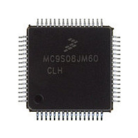
MC9S08JM60CLH Freescale, MC9S08JM60CLH Datasheet - Page 67

MC9S08JM60CLH
Manufacturer Part Number
MC9S08JM60CLH
Description
Manufacturer
Freescale
Datasheet
1.MC9S08JM60CLH.pdf
(388 pages)
Specifications of MC9S08JM60CLH
Cpu Family
HCS08
Device Core Size
8b
Frequency (max)
24MHz
Interface Type
SCI/SPI
Total Internal Ram Size
4KB
# I/os (max)
51
Number Of Timers - General Purpose
8
Operating Supply Voltage (typ)
3.3/5V
Operating Supply Voltage (max)
5.5V
Operating Supply Voltage (min)
2.7V
On-chip Adc
12-chx12-bit
Instruction Set Architecture
CISC
Operating Temp Range
-40C to 85C
Operating Temperature Classification
Industrial
Mounting
Surface Mount
Pin Count
64
Package Type
LQFP
Program Memory Type
Flash
Program Memory Size
60KB
Lead Free Status / RoHS Status
Compliant
Available stocks
Company
Part Number
Manufacturer
Quantity
Price
Company:
Part Number:
MC9S08JM60CLH
Manufacturer:
Freescale Semiconductor
Quantity:
10 000
Part Number:
MC9S08JM60CLH
Manufacturer:
FREESCALE
Quantity:
20 000
Company:
Part Number:
MC9S08JM60CLHE
Manufacturer:
AZBIL
Quantity:
1 000
- Current page: 67 of 388
- Download datasheet (5Mb)
5.5
Interrupts provide a way to save the current CPU status and registers, execute an interrupt service routine
(ISR), and then restore the CPU status so processing resumes where it left off before the interrupt. Other
than the software interrupt (SWI), which is a program instruction, interrupts are caused by hardware events
such as an edge on the IRQ pin or a timer-overflow event. The debug module can also generate an SWI
under certain circumstances.
If an event occurs in an enabled interrupt source, an associated read-only status flag will become set. The
CPU will not respond until and unless the local interrupt enable is a logic 1 to enable the interrupt. The
I bit in the CCR is 0 to allow interrupts. The global interrupt mask (I bit) in the CCR is initially set after
reset which masks (prevents) all maskable interrupt sources. The user program initializes the stack pointer
and performs other system setup before clearing the I bit to allow the CPU to respond to interrupts.
When the CPU receives a qualified interrupt request, it completes the current instruction before responding
to the interrupt. The interrupt sequence obeys the same cycle-by-cycle sequence as the SWI instruction
and consists of:
While the CPU is responding to the interrupt, the I bit is automatically set to avoid the possibility of
another interrupt interrupting the ISR itself (this is called nesting of interrupts). Normally, the I bit is
restored to 0 when the CCR is restored from the value stacked on entry to the ISR. In rare cases, the I bit
may be cleared inside an ISR (after clearing the status flag that generated the interrupt) so that other
interrupts can be serviced without waiting for the first service routine to finish. This practice is not
recommended for anyone other than the most experienced programmers because it can lead to subtle
program errors that are difficult to debug.
The interrupt service routine ends with a return-from-interrupt (RTI) instruction which restores the CCR,
A, X, and PC registers to their pre-interrupt values by reading the previously saved information off the
stack.
When two or more interrupts are pending when the I bit is cleared, the highest priority source is serviced
first (see
Freescale Semiconductor
•
•
•
•
Saving the CPU registers on the stack
Setting the I bit in the CCR to mask further interrupts
Fetching the interrupt vector for the highest-priority interrupt that is currently pending
Filling the instruction queue with the first three bytes of program information starting from the
address fetched from the interrupt vector locations
Table
Interrupts
For compatibility with the M68HC08, the H register is not automatically
saved and restored. It is good programming practice to push H onto the stack
at the start of the interrupt service routine (ISR) and restore it immediately
before the RTI that is used to return from the ISR.
5-1).
MC9S08JM60 Series Data Sheet, Rev. 3
NOTE
Chapter 5 Resets, Interrupts, and System Configuration
67
Related parts for MC9S08JM60CLH
Image
Part Number
Description
Manufacturer
Datasheet
Request
R

Part Number:
Description:
TOWER ELEVATOR BOARDS HARDWARE
Manufacturer:
Freescale Semiconductor
Datasheet:

Part Number:
Description:
TOWER SERIAL I/O HARDWARE
Manufacturer:
Freescale Semiconductor
Datasheet:

Part Number:
Description:
LCD MODULE FOR TWR SYSTEM
Manufacturer:
Freescale Semiconductor
Datasheet:

Part Number:
Description:
DAUGHTER LCD WVGA I.MX51
Manufacturer:
Freescale Semiconductor
Datasheet:

Part Number:
Description:
TOWER SYSTEM BOARD MPC5125
Manufacturer:
Freescale Semiconductor
Datasheet:

Part Number:
Description:
KIT EVALUATION I.MX51
Manufacturer:
Freescale Semiconductor
Datasheet:

Part Number:
Description:
KIT DEVELOPMENT WINCE IMX25
Manufacturer:
Freescale Semiconductor
Datasheet:

Part Number:
Description:
TOWER SYSTEM KIT MPC5125
Manufacturer:
Freescale Semiconductor
Datasheet:

Part Number:
Description:
TOWER SYSTEM BOARD K40X256
Manufacturer:
Freescale Semiconductor
Datasheet:

Part Number:
Description:
TOWER SYSTEM KIT K40X256
Manufacturer:
Freescale Semiconductor
Datasheet:

Part Number:
Description:
Microcontrollers (MCU) MX28 PLATFORM DEV KIT
Manufacturer:
Freescale Semiconductor
Datasheet:

Part Number:
Description:
MCU, MPU & DSP Development Tools IAR KickStart Kit for Kinetis K60
Manufacturer:
Freescale Semiconductor
Datasheet:

Part Number:
Description:
24BIT HDMI MX535/08
Manufacturer:
Freescale Semiconductor
Datasheet:
Part Number:
Description:
Manufacturer:
Freescale Semiconductor, Inc
Datasheet:
Part Number:
Description:
Manufacturer:
Freescale Semiconductor, Inc
Datasheet:


