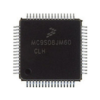
MC9S08JM60CLH Freescale, MC9S08JM60CLH Datasheet - Page 316

MC9S08JM60CLH
Manufacturer Part Number
MC9S08JM60CLH
Description
Manufacturer
Freescale
Datasheet
1.MC9S08JM60CLH.pdf
(388 pages)
Specifications of MC9S08JM60CLH
Cpu Family
HCS08
Device Core Size
8b
Frequency (max)
24MHz
Interface Type
SCI/SPI
Total Internal Ram Size
4KB
# I/os (max)
51
Number Of Timers - General Purpose
8
Operating Supply Voltage (typ)
3.3/5V
Operating Supply Voltage (max)
5.5V
Operating Supply Voltage (min)
2.7V
On-chip Adc
12-chx12-bit
Instruction Set Architecture
CISC
Operating Temp Range
-40C to 85C
Operating Temperature Classification
Industrial
Mounting
Surface Mount
Pin Count
64
Package Type
LQFP
Program Memory Type
Flash
Program Memory Size
60KB
Lead Free Status / RoHS Status
Compliant
Available stocks
Company
Part Number
Manufacturer
Quantity
Price
Company:
Part Number:
MC9S08JM60CLH
Manufacturer:
Freescale Semiconductor
Quantity:
10 000
Part Number:
MC9S08JM60CLH
Manufacturer:
FREESCALE
Quantity:
20 000
Company:
Part Number:
MC9S08JM60CLHE
Manufacturer:
AZBIL
Quantity:
1 000
- Current page: 316 of 388
- Download datasheet (5Mb)
Universal Serial Bus Device Controller (S08USBV1)
17.4.2
To efficiently manage USB endpoint communications, the USB module implements a buffer descriptor
table (BDT) comprised of buffer descriptors (BD) in the local USB RAM. The BD entries provide status
or control information for a corresponding endpoint. The BD entries also provide an address to the
endpoint’s buffer. A single BD for an endpoint direction requires 3-bytes. A detailed description of the
BDT format is provided in the next sections.
The software API intelligently manages buffers for the USB module by updating the BDT when needed.
This allows the USB module to efficiently handle data transmission and reception, while the
microcontroller performs communication overhead processing and other function dependent applications.
Because the buffers are shared between the microcontroller and the USB module, a simple semaphore
mechanism is used to distinguish who is allowed to update the BDT and buffers in buffer memory. A
semaphore bit, the OWN bit, is cleared to 0 when the BD entry is owned by the microcontroller. The
microcontroller is allowed read and write access to the BD entry and the data buffer when the OWN bit is
0. When the OWN bit is set to 1, the BD entry and the data buffer are owned by the USB module. The USB
module now has full read and write access and the microcontroller must not modify the BD or its
corresponding data buffer.
17.4.2.1
Every endpoint direction requires at least one three-byte Buffer Descriptor entry. Thus, endpoint 0, a
bidirectional control endpoint, requires one BDT entry for the IN direction, and one for the OUT direction.
Using two BD entries also allows for double-buffering. Double-buffering BDs allows the USB module to
easily transfer data at the maximum throughput provided by the USB module. Double buffering allows the
MCU to process one BD while the USB module is processing the other BD.
To facilitate double-buffering, two buffer descriptor (BD) entries are needed for each endpoint direction.
One BD entry is the EVEN BD and the other is the ODD BD.
17.4.2.2
The BDT addressing is hardwired into the module. The BDT occupies the first portion of the USB RAM.
To access endpoint data via the USB or MCU, the addressing mechanism of the buffer descriptor table
must be understood.
All enabled IN and OUT endpoint BD entries are indexed into the BDT to allow easy access via the USB
module or the MCU. The figure below shows the USB RAM organization. The figure shows that the first
entries in the USB RAM are dedicated to storage of the BDT entries - i.e. the first 30 bytes of the USB
RAM (0x00 to 0x1D) are used to implement the BDT.
316
Buffer Descriptor Table (BDT)
Multiple Buffer Descriptor Table Entries for a Single Endpoint
Addressing Buffer Descriptor Table Entries
MC9S08JM60 Series Data Sheet, Rev. 3
Freescale Semiconductor
Related parts for MC9S08JM60CLH
Image
Part Number
Description
Manufacturer
Datasheet
Request
R

Part Number:
Description:
TOWER ELEVATOR BOARDS HARDWARE
Manufacturer:
Freescale Semiconductor
Datasheet:

Part Number:
Description:
TOWER SERIAL I/O HARDWARE
Manufacturer:
Freescale Semiconductor
Datasheet:

Part Number:
Description:
LCD MODULE FOR TWR SYSTEM
Manufacturer:
Freescale Semiconductor
Datasheet:

Part Number:
Description:
DAUGHTER LCD WVGA I.MX51
Manufacturer:
Freescale Semiconductor
Datasheet:

Part Number:
Description:
TOWER SYSTEM BOARD MPC5125
Manufacturer:
Freescale Semiconductor
Datasheet:

Part Number:
Description:
KIT EVALUATION I.MX51
Manufacturer:
Freescale Semiconductor
Datasheet:

Part Number:
Description:
KIT DEVELOPMENT WINCE IMX25
Manufacturer:
Freescale Semiconductor
Datasheet:

Part Number:
Description:
TOWER SYSTEM KIT MPC5125
Manufacturer:
Freescale Semiconductor
Datasheet:

Part Number:
Description:
TOWER SYSTEM BOARD K40X256
Manufacturer:
Freescale Semiconductor
Datasheet:

Part Number:
Description:
TOWER SYSTEM KIT K40X256
Manufacturer:
Freescale Semiconductor
Datasheet:

Part Number:
Description:
Microcontrollers (MCU) MX28 PLATFORM DEV KIT
Manufacturer:
Freescale Semiconductor
Datasheet:

Part Number:
Description:
MCU, MPU & DSP Development Tools IAR KickStart Kit for Kinetis K60
Manufacturer:
Freescale Semiconductor
Datasheet:

Part Number:
Description:
24BIT HDMI MX535/08
Manufacturer:
Freescale Semiconductor
Datasheet:
Part Number:
Description:
Manufacturer:
Freescale Semiconductor, Inc
Datasheet:
Part Number:
Description:
Manufacturer:
Freescale Semiconductor, Inc
Datasheet:


