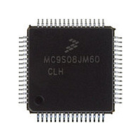
MC9S08JM60CLH Freescale, MC9S08JM60CLH Datasheet - Page 322

MC9S08JM60CLH
Manufacturer Part Number
MC9S08JM60CLH
Description
Manufacturer
Freescale
Datasheet
1.MC9S08JM60CLH.pdf
(388 pages)
Specifications of MC9S08JM60CLH
Cpu Family
HCS08
Device Core Size
8b
Frequency (max)
24MHz
Interface Type
SCI/SPI
Total Internal Ram Size
4KB
# I/os (max)
51
Number Of Timers - General Purpose
8
Operating Supply Voltage (typ)
3.3/5V
Operating Supply Voltage (max)
5.5V
Operating Supply Voltage (min)
2.7V
On-chip Adc
12-chx12-bit
Instruction Set Architecture
CISC
Operating Temp Range
-40C to 85C
Operating Temperature Classification
Industrial
Mounting
Surface Mount
Pin Count
64
Package Type
LQFP
Program Memory Type
Flash
Program Memory Size
60KB
Lead Free Status / RoHS Status
Compliant
Available stocks
Company
Part Number
Manufacturer
Quantity
Price
Company:
Part Number:
MC9S08JM60CLH
Manufacturer:
Freescale Semiconductor
Quantity:
10 000
Part Number:
MC9S08JM60CLH
Manufacturer:
FREESCALE
Quantity:
20 000
Company:
Part Number:
MC9S08JM60CLHE
Manufacturer:
AZBIL
Quantity:
1 000
- Current page: 322 of 388
- Download datasheet (5Mb)
Universal Serial Bus Device Controller (S08USBV1)
17.4.4.3
The USB includes a number of error checking and recovery mechanisms to ensure reliable data transfer.
One such exception occurs when the host sends a SETUP packet to a device, and the host never receives
the acknowledge handshake from the device. In this case, the host will retry the SETUP packet.
Endpoint 0 request handlers on the device must be aware of the possibility that after receiving a correct
SETUP packet, they could receive another SETUP packet before the data phase actually begins.
17.4.5
The USB host allocates time in 1.0 ms chunks called “Frames” for the purposes of packet scheduling. The
USB host starts each frame with a broadcast token called SOF (start of frame) that includes an 11-bit
sequence number. The TOKSOF interrupt is used to notify firmware when an SOF token was received.
Firmware can read the current frame number from the FRMNUML/FRMNUMH registers.
In general, the SOF interrupt is only monitored by devices using isochronous endpoints to help ensure that
the device and host remain synchronized.
322
2. Create BDT entries for Endpoint 0 OUT, and set the DTS and OWN bits to 1.
3. Wait for interrupt TOKDNE.
4. Read STAT register.
5. Read Endpoint 0 OUT BD.
6. Decode and process the setup packet.
7. After processing the data phase (if there was one), create a zero-byte status phase transaction.
— The status register must show Endpoint 0, RX. If it does not, then assert the EPSTALL bit in
— Verify that the token type is a SETUP token. If it is not, then assert the EPSTALL bit in the
— If the direction field in the setup packet indicates an OUT transfer, then process the out data
— If the direction field in the setup packet indicates an IN transfer, then process the in data phase
— This is accomplished for an OUT data phase (IN status phase) by setting the BC to 0 in the next
— Firmware can verify completion of the data phase by verifying the received token in the BD on
the endpoint control register.
endpoint control register.
phase to receive exactly the number of bytes specified in the wLength field of the setup packet.
to deliver no more than the number of bytes specified in the wLength field. Note that it is
common for the host to request more bytes than it needs, expecting the device to only send as
much as it needs to.
BD, while also setting OWN=1. For an IN data phase (OUT status phase), the host will send a
zero-byte packet to the device.
receipt of the TOKDNE interrupt. If the data phase was of type IN, then the status phase token
will be OUT. If the data phase was of type OUT, then the status phase token will be IN.
Start of Frame Processing
Endpoint 0 Exception Conditions
MC9S08JM60 Series Data Sheet, Rev. 3
Freescale Semiconductor
Related parts for MC9S08JM60CLH
Image
Part Number
Description
Manufacturer
Datasheet
Request
R

Part Number:
Description:
TOWER ELEVATOR BOARDS HARDWARE
Manufacturer:
Freescale Semiconductor
Datasheet:

Part Number:
Description:
TOWER SERIAL I/O HARDWARE
Manufacturer:
Freescale Semiconductor
Datasheet:

Part Number:
Description:
LCD MODULE FOR TWR SYSTEM
Manufacturer:
Freescale Semiconductor
Datasheet:

Part Number:
Description:
DAUGHTER LCD WVGA I.MX51
Manufacturer:
Freescale Semiconductor
Datasheet:

Part Number:
Description:
TOWER SYSTEM BOARD MPC5125
Manufacturer:
Freescale Semiconductor
Datasheet:

Part Number:
Description:
KIT EVALUATION I.MX51
Manufacturer:
Freescale Semiconductor
Datasheet:

Part Number:
Description:
KIT DEVELOPMENT WINCE IMX25
Manufacturer:
Freescale Semiconductor
Datasheet:

Part Number:
Description:
TOWER SYSTEM KIT MPC5125
Manufacturer:
Freescale Semiconductor
Datasheet:

Part Number:
Description:
TOWER SYSTEM BOARD K40X256
Manufacturer:
Freescale Semiconductor
Datasheet:

Part Number:
Description:
TOWER SYSTEM KIT K40X256
Manufacturer:
Freescale Semiconductor
Datasheet:

Part Number:
Description:
Microcontrollers (MCU) MX28 PLATFORM DEV KIT
Manufacturer:
Freescale Semiconductor
Datasheet:

Part Number:
Description:
MCU, MPU & DSP Development Tools IAR KickStart Kit for Kinetis K60
Manufacturer:
Freescale Semiconductor
Datasheet:

Part Number:
Description:
24BIT HDMI MX535/08
Manufacturer:
Freescale Semiconductor
Datasheet:
Part Number:
Description:
Manufacturer:
Freescale Semiconductor, Inc
Datasheet:
Part Number:
Description:
Manufacturer:
Freescale Semiconductor, Inc
Datasheet:


