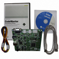
DEMO9S12XEP100 Freescale Semiconductor, DEMO9S12XEP100 Datasheet - Page 340

DEMO9S12XEP100
Manufacturer Part Number
DEMO9S12XEP100
Description
BOARD DEMO FOR MC9S12XEP100
Manufacturer
Freescale Semiconductor
Type
MCUr
Datasheet
1.EVB9S12XEP100.pdf
(1328 pages)
Specifications of DEMO9S12XEP100
Contents
Board, Cables, CD
Processor To Be Evaluated
MC9S12XEP100
Data Bus Width
16 bit
Interface Type
RS-232
Silicon Manufacturer
Freescale
Core Architecture
S12
Core Sub-architecture
S12
Silicon Core Number
MC9S12
Silicon Family Name
S12XE
Rohs Compliant
Yes
For Use With/related Products
MC9S12XEP100
Lead Free Status / RoHS Status
Lead free / RoHS Compliant
Available stocks
Company
Part Number
Manufacturer
Quantity
Price
Company:
Part Number:
DEMO9S12XEP100
Manufacturer:
PANASONIC
Quantity:
46 000
Company:
Part Number:
DEMO9S12XEP100
Manufacturer:
Freescale Semiconductor
Quantity:
135
- Current page: 340 of 1328
- Download datasheet (9Mb)
Chapter 8 S12X Debug (S12XDBGV3) Module
8.4.5.3.1
The format of the control information byte is dependent upon the active trace mode as described below. In
Normal, Loop1, or Pure PC modes tracing of XGATE activity, XINF is used to store control information.
In Normal, Loop1, or Pure PC modes tracing of CPU12X activity, CINF is used to store control
information. In Detail Mode, CXINF contains the control information
XGATE Information Byte
Figure 8-24
thread starting at SOT1 and continuing at COT1 after the higher priority thread2 has ended.
340
Because of an order from the United States International Trade Commission, BGA-packaged product lines and partnumbers
XGATE info bit setting
XGATE FLOW
XSD
XSOT
XCOT
XSOT
XCOT
indicated here currently are not available from Freescale for import or sale in the United States prior to September 2010
Field
XSD
XDV
7
6
5
4
indicates the XGATE information bit setting when switching between threads, the initial
Source Destination Indicator — This bit indicates if the corresponding stored address is a source or destination
address. This is only used in Normal and Loop1 mode tracing.
0 Source address
1 Destination address or Start of Thread or Continuation of Thread
Start Of Thread Indicator — This bit indicates that the corresponding stored address is a start of thread
address. This is only used in Normal and Loop1 mode tracing.
NOTE. This bit only has effect on devices where the XGATE module supports multiple interrupt levels.
0 Stored address not from a start of thread
1 Stored address from a start of thread
Continuation Of Thread Indicator — This bit indicates that the corresponding stored address is the first
address following a return from a higher priority thread. This is only used in Normal and Loop1 mode tracing.
NOTE. This bit only has effect on devices where the XGATE module supports multiple interrupt levels.
0 Stored address not from a continuation of thread
1 Stored address from a continuation of thread
Data Invalid Indicator — This bit indicates if the trace buffer entry is invalid. It is only used when tracing from
both sources in Normal, Loop1 and Pure PC modes, to indicate that the XGATE trace buffer entry is valid.
0 Trace buffer entry is invalid
1 Trace buffer entry is valid
Information Byte Organization
Bit 7
XSD
SOT1
XSOT
Bit 6
MC9S12XE-Family Reference Manual , Rev. 1.23
Figure 8-23. XGATE Information Byte XINF
XCOT
Table 8-44. XINF Field Descriptions
Figure 8-24. XGATE info bit setting
Bit 5
SOT2
Bit 4
XDV
Description
Bit 3
0
JAL
Bit 2
0
RTS
Bit 1
0
COT1
Freescale Semiconductor
Bit 0
0
RTS
Related parts for DEMO9S12XEP100
Image
Part Number
Description
Manufacturer
Datasheet
Request
R
Part Number:
Description:
Manufacturer:
Freescale Semiconductor, Inc
Datasheet:
Part Number:
Description:
Manufacturer:
Freescale Semiconductor, Inc
Datasheet:
Part Number:
Description:
Manufacturer:
Freescale Semiconductor, Inc
Datasheet:
Part Number:
Description:
Manufacturer:
Freescale Semiconductor, Inc
Datasheet:
Part Number:
Description:
Manufacturer:
Freescale Semiconductor, Inc
Datasheet:
Part Number:
Description:
Manufacturer:
Freescale Semiconductor, Inc
Datasheet:
Part Number:
Description:
Manufacturer:
Freescale Semiconductor, Inc
Datasheet:
Part Number:
Description:
Manufacturer:
Freescale Semiconductor, Inc
Datasheet:
Part Number:
Description:
Manufacturer:
Freescale Semiconductor, Inc
Datasheet:
Part Number:
Description:
Manufacturer:
Freescale Semiconductor, Inc
Datasheet:
Part Number:
Description:
Manufacturer:
Freescale Semiconductor, Inc
Datasheet:
Part Number:
Description:
Manufacturer:
Freescale Semiconductor, Inc
Datasheet:
Part Number:
Description:
Manufacturer:
Freescale Semiconductor, Inc
Datasheet:
Part Number:
Description:
Manufacturer:
Freescale Semiconductor, Inc
Datasheet:
Part Number:
Description:
Manufacturer:
Freescale Semiconductor, Inc
Datasheet:


