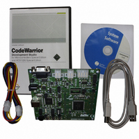
DEMO9S12XEP100 Freescale Semiconductor, DEMO9S12XEP100 Datasheet - Page 377

DEMO9S12XEP100
Manufacturer Part Number
DEMO9S12XEP100
Description
BOARD DEMO FOR MC9S12XEP100
Manufacturer
Freescale Semiconductor
Type
MCUr
Datasheet
1.EVB9S12XEP100.pdf
(1328 pages)
Specifications of DEMO9S12XEP100
Contents
Board, Cables, CD
Processor To Be Evaluated
MC9S12XEP100
Data Bus Width
16 bit
Interface Type
RS-232
Silicon Manufacturer
Freescale
Core Architecture
S12
Core Sub-architecture
S12
Silicon Core Number
MC9S12
Silicon Family Name
S12XE
Rohs Compliant
Yes
For Use With/related Products
MC9S12XEP100
Lead Free Status / RoHS Status
Lead free / RoHS Compliant
Available stocks
Company
Part Number
Manufacturer
Quantity
Price
Company:
Part Number:
DEMO9S12XEP100
Manufacturer:
PANASONIC
Quantity:
46 000
Company:
Part Number:
DEMO9S12XEP100
Manufacturer:
Freescale Semiconductor
Quantity:
135
- Current page: 377 of 1328
- Download datasheet (9Mb)
Chapter 10 XGATE (S12XGATEV3)
The programmer’s model of the XGATE RISC core is shown in
Figure
10-22. The processor offers a set
of seven general purpose registers (R1 - R7), which serve as accumulators and index registers. An
additional eighth register (R0) is tied to the value “$0000”. Registers R1 and R7 have additional
functionality. R1 is preloaded with the initial data pointer of the channel’s service request vector (see
Figure
10-23). R7 is either preloaded with the content of XGISP74 if the interrupt priority of the current
channel is in the range 7 to 4, or it is with preloaded the content of XGISP31 if the interrupt priority of the
current channel is in the range 3 to 1. The remaining general purpose registers will be reset to an
unspecified value at the beginning of each thread.
The 16 bit program counter allows the addressing of a 64 kbyte address space.
The condition code register contains four bits: the sign bit (S), the zero flag (Z), the overflow flag (V), and
the carry bit (C). The initial content of the condition code register is undefined.
10.4.3
Memory Map
The XGATE’s RISC core is able to access an address space of 64K bytes. The allocation of memory blocks
within this address space is determined on chip level. Refer to the S12X_MMC Section for a detailed
information.
The XGATE vector block assigns a start address and a data pointer to each XGATE channel. Its position
in the XGATE memory map can be adjusted through the XGVBR register (see
Section 10.3.1.7, “XGATE
Vector Base Address Register
(XGVBR)”).
Figure 10-23
shows the layout of the vector block. Each vector
consists of two 16 bit words. The first contains the start address of the service routine. This value will be
loaded into the program counter before a service routine is executed. The second word is a pointer to the
service routine’s data space. This value will be loaded into register R1 before a service routine is executed.
MC9S12XE-Family Reference Manual Rev. 1.23
Freescale Semiconductor
377
Because of an order from the United States International Trade Commission, BGA-packaged product lines and partnumbers
indicated here currently are not available from Freescale for import or sale in the United States prior to September 2010
Related parts for DEMO9S12XEP100
Image
Part Number
Description
Manufacturer
Datasheet
Request
R
Part Number:
Description:
Manufacturer:
Freescale Semiconductor, Inc
Datasheet:
Part Number:
Description:
Manufacturer:
Freescale Semiconductor, Inc
Datasheet:
Part Number:
Description:
Manufacturer:
Freescale Semiconductor, Inc
Datasheet:
Part Number:
Description:
Manufacturer:
Freescale Semiconductor, Inc
Datasheet:
Part Number:
Description:
Manufacturer:
Freescale Semiconductor, Inc
Datasheet:
Part Number:
Description:
Manufacturer:
Freescale Semiconductor, Inc
Datasheet:
Part Number:
Description:
Manufacturer:
Freescale Semiconductor, Inc
Datasheet:
Part Number:
Description:
Manufacturer:
Freescale Semiconductor, Inc
Datasheet:
Part Number:
Description:
Manufacturer:
Freescale Semiconductor, Inc
Datasheet:
Part Number:
Description:
Manufacturer:
Freescale Semiconductor, Inc
Datasheet:
Part Number:
Description:
Manufacturer:
Freescale Semiconductor, Inc
Datasheet:
Part Number:
Description:
Manufacturer:
Freescale Semiconductor, Inc
Datasheet:
Part Number:
Description:
Manufacturer:
Freescale Semiconductor, Inc
Datasheet:
Part Number:
Description:
Manufacturer:
Freescale Semiconductor, Inc
Datasheet:
Part Number:
Description:
Manufacturer:
Freescale Semiconductor, Inc
Datasheet:


