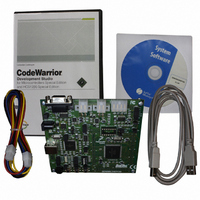
DEMO9S12XEP100 Freescale Semiconductor, DEMO9S12XEP100 Datasheet - Page 674

DEMO9S12XEP100
Manufacturer Part Number
DEMO9S12XEP100
Description
BOARD DEMO FOR MC9S12XEP100
Manufacturer
Freescale Semiconductor
Type
MCUr
Datasheet
1.EVB9S12XEP100.pdf
(1328 pages)
Specifications of DEMO9S12XEP100
Contents
Board, Cables, CD
Processor To Be Evaluated
MC9S12XEP100
Data Bus Width
16 bit
Interface Type
RS-232
Silicon Manufacturer
Freescale
Core Architecture
S12
Core Sub-architecture
S12
Silicon Core Number
MC9S12
Silicon Family Name
S12XE
Rohs Compliant
Yes
For Use With/related Products
MC9S12XEP100
Lead Free Status / RoHS Status
Lead free / RoHS Compliant
Available stocks
Company
Part Number
Manufacturer
Quantity
Price
Company:
Part Number:
DEMO9S12XEP100
Manufacturer:
PANASONIC
Quantity:
46 000
Company:
Part Number:
DEMO9S12XEP100
Manufacturer:
Freescale Semiconductor
Quantity:
135
- Current page: 674 of 1328
- Download datasheet (9Mb)
Chapter 17 Periodic Interrupt Timer (S12PIT24B8CV2)
17.4.1
As shown in
16-bit modulus down-counters and two 8-bit modulus down-counters. The 16-bit timers are clocked with
two selectable micro time bases which are generated with 8-bit modulus down-counters. Each 16-bit timer
is connected to micro time base 0 or 1 via the PMUX[7:0] bit setting in the PIT Multiplex (PITMUX)
register.
A timer channel is enabled if the module enable bit PITE in the PIT control and force load micro timer
(PITCFLMT) register is set and if the corresponding PCE bit in the PIT channel enable (PITCE) register
is set. Two 8-bit modulus down-counters are used to generate two micro time bases. As soon as a micro
time base is selected for an enabled timer channel, the corresponding micro timer modulus down-counter
will load its start value as specified in the PITMTLD0 or PITMTLD1 register and will start down-counting.
Whenever the micro timer down-counter has counted to zero the PITMTLD register is reloaded and the
connected 16-bit modulus down-counters count one cycle.
Whenever a 16-bit timer counter and the connected 8-bit micro timer counter have counted to zero, the
PITLD register is reloaded and the corresponding time-out flag PTF in the PIT time-out flag (PITTF)
register is set, as shown in
micro timer load (PITMTLD) registers and the bus clock f
For example, for a 40 MHz bus clock, the maximum time-out period equals:
The current 16-bit modulus down-counter value can be read via the PITCNT register. The micro timer
down-counter values cannot be read.
The 8-bit micro timers can individually be restarted by writing a one to the corresponding force load micro
timer PFLMT bits in the PIT control and force load micro timer (PITCFLMT) register. The 16-bit timers
can individually be restarted by writing a one to the corresponding force load timer PFLT bits in the PIT
forceload timer (PITFLT) register. If desired, any group of timers and micro timers can be restarted at the
same time by using one 16-bit write to the adjacent PITCFLMT and PITFLT registers with the relevant
bits set, as shown in
674
Because of an order from the United States International Trade Commission, BGA-packaged product lines and partnumbers
indicated here currently are not available from Freescale for import or sale in the United States prior to September 2010
time-out period = (PITMTLD + 1) * (PITLD + 1) / f
256 * 65536 * 25 ns = 419.43 ms.
Timer
Figure 17-1
Figure
and
Figure
17-28.
Figure
MC9S12XE-Family Reference Manual , Rev. 1.23
17-28. The time-out period is a function of the timer load (PITLD) and
17-27, the 24-bit timers are built in a two-stage architecture with eight
BUS
BUS
:
.
Freescale Semiconductor
Related parts for DEMO9S12XEP100
Image
Part Number
Description
Manufacturer
Datasheet
Request
R
Part Number:
Description:
Manufacturer:
Freescale Semiconductor, Inc
Datasheet:
Part Number:
Description:
Manufacturer:
Freescale Semiconductor, Inc
Datasheet:
Part Number:
Description:
Manufacturer:
Freescale Semiconductor, Inc
Datasheet:
Part Number:
Description:
Manufacturer:
Freescale Semiconductor, Inc
Datasheet:
Part Number:
Description:
Manufacturer:
Freescale Semiconductor, Inc
Datasheet:
Part Number:
Description:
Manufacturer:
Freescale Semiconductor, Inc
Datasheet:
Part Number:
Description:
Manufacturer:
Freescale Semiconductor, Inc
Datasheet:
Part Number:
Description:
Manufacturer:
Freescale Semiconductor, Inc
Datasheet:
Part Number:
Description:
Manufacturer:
Freescale Semiconductor, Inc
Datasheet:
Part Number:
Description:
Manufacturer:
Freescale Semiconductor, Inc
Datasheet:
Part Number:
Description:
Manufacturer:
Freescale Semiconductor, Inc
Datasheet:
Part Number:
Description:
Manufacturer:
Freescale Semiconductor, Inc
Datasheet:
Part Number:
Description:
Manufacturer:
Freescale Semiconductor, Inc
Datasheet:
Part Number:
Description:
Manufacturer:
Freescale Semiconductor, Inc
Datasheet:
Part Number:
Description:
Manufacturer:
Freescale Semiconductor, Inc
Datasheet:


