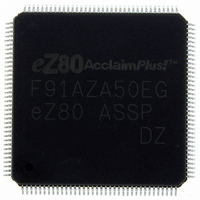
EZ80F91AZA50EG Zilog, EZ80F91AZA50EG Datasheet - Page 240

EZ80F91AZA50EG
Manufacturer Part Number
EZ80F91AZA50EG
Description
IC ACCLAIM MCU 256KB 144LQFP
Manufacturer
Zilog
Series
eZ80® AcclaimPlus!™r
Datasheet
1.EZ80F91AZA50SG.pdf
(387 pages)
Specifications of EZ80F91AZA50EG
Core Processor
Z8
Core Size
8-Bit
Speed
50MHz
Connectivity
Ethernet, I²C, IrDA, SPI, UART/USART
Peripherals
Brown-out Detect/Reset, POR, PWM, WDT
Number Of I /o
32
Program Memory Size
256KB (256K x 8)
Program Memory Type
FLASH
Ram Size
16K x 8
Voltage - Supply (vcc/vdd)
3 V ~ 3.6 V
Oscillator Type
Internal
Operating Temperature
-40°C ~ 105°C
Package / Case
144-LQFP
Processor Series
EZ80F91x
Core
eZ80
Data Bus Width
8 bit
Data Ram Size
16 KB
Interface Type
I2C, IrDA, SPI
Maximum Clock Frequency
50 MHz
Number Of Programmable I/os
32
Number Of Timers
4
Operating Supply Voltage
3 V to 3.6 V
Maximum Operating Temperature
+ 105 C
Mounting Style
SMD/SMT
Development Tools By Supplier
eZ80F910300ZCOG
Minimum Operating Temperature
- 40 C
For Use With
269-4712 - KIT DEV ENCORE 32 SERIES269-4671 - BOARD ZDOTS SBC Z80ACCLAIM PLUS269-4561 - KIT DEV FOR EZ80F91 W/C-COMPILER269-4560 - KIT DEV FOR EZ80F91 W/C-COMPILER
Lead Free Status / RoHS Status
Lead free / RoHS Compliant
Eeprom Size
-
Data Converters
-
Lead Free Status / Rohs Status
Details
Other names
269-4563
Available stocks
Company
Part Number
Manufacturer
Quantity
Price
- Current page: 240 of 387
- Download datasheet (5Mb)
Table 130. I
PS027001-0707
Bit
Reset
CPU Access
Note: W = Read only.
Bit
Position
7
[6:3]
M
[2:0]
N
2
C Clock Control Registers
I
The I
which the I
is in MASTER mode. The Write Only I
the Read Only I2C_SR registers. See
The I
of this system clock is f
f
In MASTER mode, the I
lowing equation:
The use of two separately-programmable dividers allows the MASTER mode output
frequency to be set independently of the frequency at which the I
feature is particularly useful in multimaster systems because the frequency at which the
I
to ensure that START and STOP conditions are always detected. By using two
2
SAMP
2
C Clock Control Register
C bus is sampled must be at least 10 times the frequency of the fastest master on the bus
Value
0
0000–1111 I
000–111
2
2
f
f
C_CCR register is a Write Only register. The seven LSBs control the frequency at
C clocks are derived from the system clock of the eZ80F91 device. The frequency
SAMP
SCL
supplied by the following equation:
2
W
=
7
0
C bus is sampled and the frequency of the I
=
10 • (M + 1)(2)
Description
Reserved.
I
2
2
f
C clock divider scalar value.
C clock divider exponent.
SCLK
2
W
6
0
N
f
SCLK
SCK
2
C clock output frequency on SCL (f
. The I
W
5
0
(I2C_CCR = 00CCh)
N
2
C bus is sampled by the I
W
4
0
Table
2
C_CCR registers share the same I/O addresses as
130.
W
3
0
W
2
0
2
C clock line (SCL) when the I
W
2
1
0
C block at the frequency
SCL
Product Specification
2
) is supplied by the fol-
C bus is sampled. This
W
0
0
I
2
C Serial I/O Interface
eZ80F91 ASSP
2
C
232
Related parts for EZ80F91AZA50EG
Image
Part Number
Description
Manufacturer
Datasheet
Request
R

Part Number:
Description:
Communication Controllers, ZILOG INTELLIGENT PERIPHERAL CONTROLLER (ZIP)
Manufacturer:
Zilog, Inc.
Datasheet:

Part Number:
Description:
KIT DEV FOR Z8 ENCORE 16K TO 64K
Manufacturer:
Zilog
Datasheet:

Part Number:
Description:
KIT DEV Z8 ENCORE XP 28-PIN
Manufacturer:
Zilog
Datasheet:

Part Number:
Description:
DEV KIT FOR Z8 ENCORE 8K/4K
Manufacturer:
Zilog
Datasheet:

Part Number:
Description:
KIT DEV Z8 ENCORE XP 28-PIN
Manufacturer:
Zilog
Datasheet:

Part Number:
Description:
DEV KIT FOR Z8 ENCORE 4K TO 8K
Manufacturer:
Zilog
Datasheet:

Part Number:
Description:
CMOS Z8 microcontroller. ROM 16 Kbytes, RAM 256 bytes, speed 16 MHz, 32 lines I/O, 3.0V to 5.5V
Manufacturer:
Zilog, Inc.
Datasheet:

Part Number:
Description:
Low-cost microcontroller. 512 bytes ROM, 61 bytes RAM, 8 MHz
Manufacturer:
Zilog, Inc.
Datasheet:

Part Number:
Description:
Z8 4K OTP Microcontroller
Manufacturer:
Zilog, Inc.
Datasheet:

Part Number:
Description:
CMOS SUPER8 ROMLESS MCU
Manufacturer:
Zilog, Inc.
Datasheet:

Part Number:
Description:
SL1866 CMOSZ8 OTP Microcontroller
Manufacturer:
Zilog, Inc.
Datasheet:

Part Number:
Description:
SL1866 CMOSZ8 OTP Microcontroller
Manufacturer:
Zilog, Inc.
Datasheet:

Part Number:
Description:
OTP (KB) = 1, RAM = 125, Speed = 12, I/O = 14, 8-bit Timers = 2, Comm Interfaces Other Features = Por, LV Protect, Voltage = 4.5-5.5V
Manufacturer:
Zilog, Inc.
Datasheet:

Part Number:
Description:
Manufacturer:
Zilog, Inc.
Datasheet:


