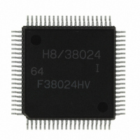
HD64F38024DV Renesas Electronics America, HD64F38024DV Datasheet - Page 140

HD64F38024DV
Manufacturer Part Number
HD64F38024DV
Description
IC H8/SLP MCU FLASH 80QFP
Manufacturer
Renesas Electronics America
Series
H8® H8/300L SLPr
Datasheets
1.US38024-BAG1.pdf
(684 pages)
2.DF36012GFYV.pdf
(1021 pages)
3.DF38102HV.pdf
(145 pages)
Specifications of HD64F38024DV
Core Processor
H8/300L
Core Size
8-Bit
Speed
10MHz
Connectivity
SCI
Peripherals
LCD, PWM, WDT
Number Of I /o
51
Program Memory Size
32KB (32K x 8)
Program Memory Type
FLASH
Ram Size
1K x 8
Voltage - Supply (vcc/vdd)
1.8 V ~ 5.5 V
Data Converters
A/D 8x10b
Oscillator Type
Internal
Operating Temperature
-40°C ~ 85°C
Package / Case
80-QFP
Lead Free Status / RoHS Status
Lead free / RoHS Compliant
Eeprom Size
-
Available stocks
Company
Part Number
Manufacturer
Quantity
Price
Company:
Part Number:
HD64F38024DV
Manufacturer:
Renesas Electronics America
Quantity:
10 000
- Current page: 140 of 684
- Download datasheet (5Mb)
Section 4 Clock Pulse Generators
amplitude of the oscillation waveform increases and the oscillation frequency stabilizes—that is,
the oscillation stabilization time—is required.
The oscillation stabilization time in the case of these state transitions is the same as the oscillation
stabilization time at power-on (the time from the point at which the power supply voltage reaches
the prescribed level until the oscillation stabilizes), specified by "oscillation stabilization time t rc "
in the AC characteristics.
Meanwhile, once the system clock has halted, a wait time of at least 8 states is necessary in order
for the CPU and peripheral functions to operate normally.
Thus, the time required from interrupt generation until operation of the CPU and peripheral
functions is the sum of the above described oscillation stabilization time and wait time. This total
time is called the oscillation stabilization wait time, and is expressed by equation (1) below.
Oscillation stabilization wait time = oscillation stabilization time + wait time
Notes: 1. H8/38024 Group
Therefore, when a transition is made from standby mode, watch mode, or subactive mode, to
active (high-speed/medium-speed) mode, with an oscillator element connected to the system clock
oscillator, careful evaluation must be carried out on the installation circuit before deciding on the
oscillation stabilization wait time. In particular, since the oscillation stabilization time is affected
by installation circuit constants, stray capacitance, and so forth, suitable constants should be
determined in consultation with the oscillator element manufacturer.
4.5.2
When a microcomputer operates, the internal power supply potential fluctuates slightly in
synchronization with the system clock. Depending on the individual crystal oscillator element
characteristics, the oscillation waveform amplitude may not be sufficiently large immediately after
the oscillation stabilization wait time, making the oscillation waveform susceptible to influence by
fluctuations in the power supply potential. In this state, the oscillation waveform may be
disrupted, leading to an unstable system clock and erroneous operation of the microcomputer.
If erroneous operation occurs, change the setting of standby timer select bits 2 to 0 (STS2 to
STS0) (bits 6 to 4 in system control register 1 (SYSCR1)) to give a longer wait time.
Rev. 8.00 Mar. 09, 2010 Page 118 of 658
REJ09B0042-0800
2. H8/38124 Group
Notes on Use of Crystal Oscillator Element (Excluding Ceramic Oscillator
Element)
= t
rc
+ (8 to 16,384 states) *
(up to 131,072 states) *
1
................. (1)
2
Related parts for HD64F38024DV
Image
Part Number
Description
Manufacturer
Datasheet
Request
R

Part Number:
Description:
KIT STARTER FOR M16C/29
Manufacturer:
Renesas Electronics America
Datasheet:

Part Number:
Description:
KIT STARTER FOR R8C/2D
Manufacturer:
Renesas Electronics America
Datasheet:

Part Number:
Description:
R0K33062P STARTER KIT
Manufacturer:
Renesas Electronics America
Datasheet:

Part Number:
Description:
KIT STARTER FOR R8C/23 E8A
Manufacturer:
Renesas Electronics America
Datasheet:

Part Number:
Description:
KIT STARTER FOR R8C/25
Manufacturer:
Renesas Electronics America
Datasheet:

Part Number:
Description:
KIT STARTER H8S2456 SHARPE DSPLY
Manufacturer:
Renesas Electronics America
Datasheet:

Part Number:
Description:
KIT STARTER FOR R8C38C
Manufacturer:
Renesas Electronics America
Datasheet:

Part Number:
Description:
KIT STARTER FOR R8C35C
Manufacturer:
Renesas Electronics America
Datasheet:

Part Number:
Description:
KIT STARTER FOR R8CL3AC+LCD APPS
Manufacturer:
Renesas Electronics America
Datasheet:

Part Number:
Description:
KIT STARTER FOR RX610
Manufacturer:
Renesas Electronics America
Datasheet:

Part Number:
Description:
KIT STARTER FOR R32C/118
Manufacturer:
Renesas Electronics America
Datasheet:

Part Number:
Description:
KIT DEV RSK-R8C/26-29
Manufacturer:
Renesas Electronics America
Datasheet:

Part Number:
Description:
KIT STARTER FOR SH7124
Manufacturer:
Renesas Electronics America
Datasheet:

Part Number:
Description:
KIT STARTER FOR H8SX/1622
Manufacturer:
Renesas Electronics America
Datasheet:


