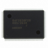
HD64F2638F20J Renesas Electronics America, HD64F2638F20J Datasheet - Page 39

HD64F2638F20J
Manufacturer Part Number
HD64F2638F20J
Description
IC H8S MCU FLASH 256K 128-QFP
Manufacturer
Renesas Electronics America
Series
H8® H8S/2600r
Specifications of HD64F2638F20J
Core Processor
H8S/2600
Core Size
16-Bit
Speed
20MHz
Connectivity
CAN, SCI, SmartCard
Peripherals
Motor Control PWM, POR, PWM, WDT
Number Of I /o
72
Program Memory Size
256KB (256K x 8)
Program Memory Type
FLASH
Ram Size
16K x 8
Voltage - Supply (vcc/vdd)
4.5 V ~ 5.5 V
Data Converters
A/D 12x10b; D/A 2x8b
Oscillator Type
Internal
Operating Temperature
-40°C ~ 85°C
Package / Case
128-QFP
Lead Free Status / RoHS Status
Contains lead / RoHS non-compliant
Eeprom Size
-
Available stocks
Company
Part Number
Manufacturer
Quantity
Price
Company:
Part Number:
HD64F2638F20J
Manufacturer:
PENESAS
Quantity:
252
- Current page: 39 of 1512
- Download datasheet (9Mb)
Section 15 I
15.1 Overview........................................................................................................................... 545
15.2 Register Descriptions ........................................................................................................ 550
15.3 Operation .......................................................................................................................... 576
15.4 Usage Notes ...................................................................................................................... 599
Section 16 Controller Area Network (HCAN)
16.1 Overview........................................................................................................................... 611
16.2 Register Descriptions ........................................................................................................ 619
REJ09B0103-0800 Rev. 8.00
May 28, 2010
15.1.1 Features................................................................................................................ 545
15.1.2 Block Diagram..................................................................................................... 546
15.1.3 Input/Output Pins ................................................................................................. 548
15.1.4 Register Configuration......................................................................................... 549
15.2.1 I
15.2.2 Slave Address Register (SAR) ............................................................................. 553
15.2.3 Second Slave Address Register (SARX) ............................................................. 554
15.2.4 I
15.2.5 I
15.2.6 I
15.2.7 Serial Control Register X (SCRX)....................................................................... 573
15.2.8 DDC Switch Register (DDCSWR) ...................................................................... 574
15.2.9 Module Stop Control Register B (MSTPCRB).................................................... 575
15.3.1 I
15.3.2 Initial Setting........................................................................................................ 578
15.3.3 Master Transmit Operation .................................................................................. 578
15.3.4 Master Receive Operation.................................................................................... 582
15.3.5 Slave Receive Operation...................................................................................... 587
15.3.6 Slave Transmit Operation .................................................................................... 592
15.3.7 IRIC Setting Timing and SCL Control ................................................................ 595
15.3.8 Operation Using the DTC .................................................................................... 596
15.3.9 Noise Canceler ..................................................................................................... 597
15.3.10 Initialization of Internal State .............................................................................. 597
16.1.1 Features................................................................................................................ 611
16.1.2 Block Diagram..................................................................................................... 613
16.1.3 Pin Configuration................................................................................................. 614
16.1.4 Register Configuration......................................................................................... 615
16.2.1 Master Control Register (MCR) .......................................................................... 619
16.2.2 General Status Register (GSR) ............................................................................ 620
16.2.3 Bit Configuration Register (BCR) ....................................................................... 622
(Only for the H8S/2638, H8S/2639, and H8S/2630)
2
2
2
2
2
2
C Bus Data Register (ICDR) ............................................................................. 550
C Bus Mode Register (ICMR)........................................................................... 555
C Bus Control Register (ICCR)......................................................................... 559
C Bus Status Register (ICSR) ........................................................................... 567
C Bus Data Format............................................................................................ 576
C Bus Interface [Option]
............................................................ 611
........................... 545
Page xxxix of l
Related parts for HD64F2638F20J
Image
Part Number
Description
Manufacturer
Datasheet
Request
R

Part Number:
Description:
KIT STARTER FOR M16C/29
Manufacturer:
Renesas Electronics America
Datasheet:

Part Number:
Description:
KIT STARTER FOR R8C/2D
Manufacturer:
Renesas Electronics America
Datasheet:

Part Number:
Description:
R0K33062P STARTER KIT
Manufacturer:
Renesas Electronics America
Datasheet:

Part Number:
Description:
KIT STARTER FOR R8C/23 E8A
Manufacturer:
Renesas Electronics America
Datasheet:

Part Number:
Description:
KIT STARTER FOR R8C/25
Manufacturer:
Renesas Electronics America
Datasheet:

Part Number:
Description:
KIT STARTER H8S2456 SHARPE DSPLY
Manufacturer:
Renesas Electronics America
Datasheet:

Part Number:
Description:
KIT STARTER FOR R8C38C
Manufacturer:
Renesas Electronics America
Datasheet:

Part Number:
Description:
KIT STARTER FOR R8C35C
Manufacturer:
Renesas Electronics America
Datasheet:

Part Number:
Description:
KIT STARTER FOR R8CL3AC+LCD APPS
Manufacturer:
Renesas Electronics America
Datasheet:

Part Number:
Description:
KIT STARTER FOR RX610
Manufacturer:
Renesas Electronics America
Datasheet:

Part Number:
Description:
KIT STARTER FOR R32C/118
Manufacturer:
Renesas Electronics America
Datasheet:

Part Number:
Description:
KIT DEV RSK-R8C/26-29
Manufacturer:
Renesas Electronics America
Datasheet:

Part Number:
Description:
KIT STARTER FOR SH7124
Manufacturer:
Renesas Electronics America
Datasheet:

Part Number:
Description:
KIT STARTER FOR H8SX/1622
Manufacturer:
Renesas Electronics America
Datasheet:


