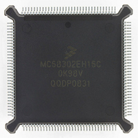
MC68302EH16C Freescale Semiconductor, MC68302EH16C Datasheet - Page 164

MC68302EH16C
Manufacturer Part Number
MC68302EH16C
Description
IC MPU MULTI-PROTOCOL 132-PQFP
Manufacturer
Freescale Semiconductor
Datasheets
1.MC68302AG20C.pdf
(4 pages)
2.MC68302AG20C.pdf
(2 pages)
3.MC68302AG20C.pdf
(13 pages)
4.MC68302EH16C.pdf
(481 pages)
Specifications of MC68302EH16C
Processor Type
M683xx 32-Bit
Speed
16MHz
Voltage
5V
Mounting Type
Surface Mount
Package / Case
132-MQFP, 132-PQFP
Controller Family/series
68K
Core Size
32 Bit
Ram Memory Size
1152Byte
Cpu Speed
16MHz
No. Of Timers
3
Embedded Interface Type
SCP, TDM
Digital Ic Case Style
PQFP
Rohs Compliant
Yes
Family Name
M68000
Device Core
ColdFire
Device Core Size
32b
Frequency (max)
16MHz
Instruction Set Architecture
RISC
Supply Voltage 1 (typ)
5V
Operating Temp Range
0C to 70C
Operating Temperature Classification
Commercial
Mounting
Surface Mount
Pin Count
132
Package Type
PQFP
Lead Free Status / RoHS Status
Lead free / RoHS Compliant
Features
-
Lead Free Status / Rohs Status
RoHS Compliant part
Electrostatic Device
Available stocks
Company
Part Number
Manufacturer
Quantity
Price
Company:
Part Number:
MC68302EH16C
Manufacturer:
Freescale Semiconductor
Quantity:
135
Company:
Part Number:
MC68302EH16C
Manufacturer:
PANA
Quantity:
99
Company:
Part Number:
MC68302EH16C
Manufacturer:
Freescale Semiconductor
Quantity:
10 000
Part Number:
MC68302EH16C
Manufacturer:
FREESCALE
Quantity:
20 000
Company:
Part Number:
MC68302EH16CB1
Manufacturer:
Freescale Semiconductor
Quantity:
10 000
Company:
Part Number:
MC68302EH16CR2
Manufacturer:
Freescale Semiconductor
Quantity:
10 000
- MC68302AG20C PDF datasheet
- MC68302AG20C PDF datasheet #2
- MC68302AG20C PDF datasheet #3
- MC68302EH16C PDF datasheet #4
- Current page: 164 of 481
- Download datasheet (2Mb)
Communications Processor (CP)
Since the transmitter and receiver work asynchronously, there is no need to connect trans-
mit and receive clocks. Instead, the receiver over-samples the incoming data stream by a
factor of 16 and uses some of these samples to determine the bit value. Traditionally, the
middle three of the 16 samples are used. Two UARTs can communicate using a system like
this if parameters such as the parity scheme and character length are the same for both
transmitter and receiver.
When data is not transmitted in the UART protocol, a continuous stream of ones is transmit-
ted. This is called the idle condition. Since the start bit is always a zero, the receiver can
detect when real data is once again present on the line. The UART also specifies an all-ze-
ros character, called a break, which is used to abort a character transfer sequence.
Many different protocols have been defined that use asynchronous characters, but the most
popular of these is the RS-232 standard. RS-232 specifies standard baud rates, handshak-
ing protocols, and mechanical/electrical details. Another popular standard using the same
character format is RS-485, which defines a balanced line system allowing longer cables
than RS-232 links. Synchronous protocols like HDLC or DDCMP are sometimes defined to
run over asynchronous links. Other protocols like PROFIBUS (see Appendix C RISC Micro-
code from RAM) extend the UART protocol to include LAN-oriented features such as token
passing.
All the standards provide handshaking signals, but some systems require just three physical
lines: transmit data, receive data, and ground.
Many proprietary standards have been built around the asynchronous character frame, and
some even implement a multidrop configuration. In multidrop systems, more than two sta-
tions may be present on a network, with each station having a specific address. Frames
composed of many characters may be broadcast, with the first character acting as a desti-
nation address. To allow this procedure, the UART frame is extended by one bit to distin-
guish between an address character and the normal data characters.
By appropriately setting the SCC mode register, any of the SCC channels may be config-
ured to function as a UART. The UART controller provides standard serial I/O using asyn-
chronous character-oriented (start-stop) protocols. The UART may be used to communicate
with other existing UART devices. Also, in conjunction with another SCC channel, it may be
used in either ISDN terminal adaptor or X.25 packet assembly and disassembly (PAD) ap-
plications.
The UART provides a port for serial communication to other microprocessors, terminals,
etc., either locally or through modems. It includes facilities for communication using stan-
dard asynchronous bit rates and protocols. The UART supports a multidrop mode for mas-
ter/slave operation with wakeup capability on either an idle line or an address bit.
The UART uses a seven-pin interface in NMSI mode. It transmits data from memory (inter-
nal or external) to the TXD line and receives data from the RXD line into memory. The seven
dedicated serial interface pins are transmit data (TXD), receive data (RXD), receive clock
(RCLK), transmit clock (TCLK), carrier detect (CD), clear to send (CTS), and request to send
4-44
MC68302 USER’S MANUAL
MOTOROLA
Related parts for MC68302EH16C
Image
Part Number
Description
Manufacturer
Datasheet
Request
R
Part Number:
Description:
Manufacturer:
Freescale Semiconductor, Inc
Datasheet:

Part Number:
Description:
MC68302 Configuring the Chip Selects on the MC68302
Manufacturer:
Motorola / Freescale Semiconductor

Part Number:
Description:
MC68302 Design Concept - Expanding Interrupts on the MC68302
Manufacturer:
Motorola / Freescale Semiconductor

Part Number:
Description:
MC68302 MC68302 Adapting a WAN Controller to a LAN Environment
Manufacturer:
Motorola / Freescale Semiconductor

Part Number:
Description:
MC68302 EKB Applications - Power Measurements on the MC68302
Manufacturer:
Motorola / Freescale Semiconductor

Part Number:
Description:
MC68302 Interfacing the MC68020 to a Slave MC68302
Manufacturer:
Motorola / Freescale Semiconductor

Part Number:
Description:
MC68302 MC68302 Software Performance
Manufacturer:
Motorola / Freescale Semiconductor

Part Number:
Description:
MC68302 Evaluating EDX on the ADS302
Manufacturer:
Motorola / Freescale Semiconductor

Part Number:
Description:
MC68302 Design Advisory #1 - MC68SC302 Passive ISDN Protocol Engine
Manufacturer:
Motorola / Freescale Semiconductor

Part Number:
Description:
MC68302, MC68360, and MPC860 Characteristics and Design Notes for Crystal Feedback Oscillators
Manufacturer:
Motorola / Freescale Semiconductor
Part Number:
Description:
Mc68302 Integrated Multi-protocol Processor
Manufacturer:
Freescale Semiconductor, Inc
Datasheet:
Part Number:
Description:
Manufacturer:
Freescale Semiconductor, Inc
Datasheet:
Part Number:
Description:
Manufacturer:
Freescale Semiconductor, Inc
Datasheet:
Part Number:
Description:
Manufacturer:
Freescale Semiconductor, Inc
Datasheet:
Part Number:
Description:
Manufacturer:
Freescale Semiconductor, Inc
Datasheet:


