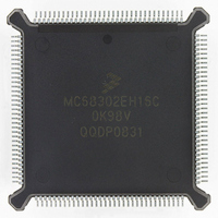
MC68302EH16C Freescale Semiconductor, MC68302EH16C Datasheet - Page 378

MC68302EH16C
Manufacturer Part Number
MC68302EH16C
Description
IC MPU MULTI-PROTOCOL 132-PQFP
Manufacturer
Freescale Semiconductor
Datasheets
1.MC68302AG20C.pdf
(4 pages)
2.MC68302AG20C.pdf
(2 pages)
3.MC68302AG20C.pdf
(13 pages)
4.MC68302EH16C.pdf
(481 pages)
Specifications of MC68302EH16C
Processor Type
M683xx 32-Bit
Speed
16MHz
Voltage
5V
Mounting Type
Surface Mount
Package / Case
132-MQFP, 132-PQFP
Controller Family/series
68K
Core Size
32 Bit
Ram Memory Size
1152Byte
Cpu Speed
16MHz
No. Of Timers
3
Embedded Interface Type
SCP, TDM
Digital Ic Case Style
PQFP
Rohs Compliant
Yes
Family Name
M68000
Device Core
ColdFire
Device Core Size
32b
Frequency (max)
16MHz
Instruction Set Architecture
RISC
Supply Voltage 1 (typ)
5V
Operating Temp Range
0C to 70C
Operating Temperature Classification
Commercial
Mounting
Surface Mount
Pin Count
132
Package Type
PQFP
Lead Free Status / RoHS Status
Lead free / RoHS Compliant
Features
-
Lead Free Status / Rohs Status
RoHS Compliant part
Electrostatic Device
Available stocks
Company
Part Number
Manufacturer
Quantity
Price
Company:
Part Number:
MC68302EH16C
Manufacturer:
Freescale Semiconductor
Quantity:
135
Company:
Part Number:
MC68302EH16C
Manufacturer:
PANA
Quantity:
99
Company:
Part Number:
MC68302EH16C
Manufacturer:
Freescale Semiconductor
Quantity:
10 000
Part Number:
MC68302EH16C
Manufacturer:
FREESCALE
Quantity:
20 000
Company:
Part Number:
MC68302EH16CB1
Manufacturer:
Freescale Semiconductor
Quantity:
10 000
Company:
Part Number:
MC68302EH16CR2
Manufacturer:
Freescale Semiconductor
Quantity:
10 000
- MC68302AG20C PDF datasheet
- MC68302AG20C PDF datasheet #2
- MC68302AG20C PDF datasheet #3
- MC68302EH16C PDF datasheet #4
- Current page: 378 of 481
- Download datasheet (2Mb)
MC68302 Applications
* These bits are cleared by writing a one or setting RST in the CMR.
Figure D-9 depicts the typical cycles used on a 16-bit bus when the source data size and
destination data size are not equal. In this example, the source size is byte and the destina-
tion size is word. The IDMA performs two read cycles to obtain data and then performs a
write cycle to place data into the destination location. If the CMR SAPI bit was set, then each
byte read increments the SAPR by two. Hence, the SAPR is always pointing to the leftmost
or rightmost byte of the 16-bit bus. This type of transfer duplicates the function of an M68000
MOVEP instruction.
D-28
Done Not Synchronized—DONE is asserted as an input
during the first access of an 8-bit peripheral when operat-
ing with 1 6-bit memory.
Bus Error Source—A bus error occurred during the read
portion of an IDMA cycle.
Bus Error Destination—A bus error occurred during the
write portion of an IDMA cycle.
Normal Channel Transfer Done—The BCR decremented
to zero or the external peripheral asserted DONE and no
errors occurred during any IDMA cycle.
DTACK
NOTE: If the byte count had reached zero, DONE would be asserted by the IDMA, indicating normal transfer termination.
DONE
(OUTPUT)
(OUTPUT)
CLKO
Figure D-8. Typical IDMA External Cycles Showing Block Transfer Termination
DTACK
BGACK
AS
DACK
CLKO
AS
Figure D-9. Typical IDMA Source to Word Destination IDMA Cycles
Operation
READ 1
S0
Table D-3. Channel Status Register Bits
S1
S2
READ CYCLE
MC68302 USER’S MANUAL
S3
S4
S5
S6
DONE
DNS
BED
BES
Bit
S7
READ 2
7
Reserved
6
WRITE CYCLE
5
4
3
1
WRITE
1*
2
MOTOROLA
1*
OUTPUT
I/O
1
INPUT
1*
0
Related parts for MC68302EH16C
Image
Part Number
Description
Manufacturer
Datasheet
Request
R
Part Number:
Description:
Manufacturer:
Freescale Semiconductor, Inc
Datasheet:

Part Number:
Description:
MC68302 Configuring the Chip Selects on the MC68302
Manufacturer:
Motorola / Freescale Semiconductor

Part Number:
Description:
MC68302 Design Concept - Expanding Interrupts on the MC68302
Manufacturer:
Motorola / Freescale Semiconductor

Part Number:
Description:
MC68302 MC68302 Adapting a WAN Controller to a LAN Environment
Manufacturer:
Motorola / Freescale Semiconductor

Part Number:
Description:
MC68302 EKB Applications - Power Measurements on the MC68302
Manufacturer:
Motorola / Freescale Semiconductor

Part Number:
Description:
MC68302 Interfacing the MC68020 to a Slave MC68302
Manufacturer:
Motorola / Freescale Semiconductor

Part Number:
Description:
MC68302 MC68302 Software Performance
Manufacturer:
Motorola / Freescale Semiconductor

Part Number:
Description:
MC68302 Evaluating EDX on the ADS302
Manufacturer:
Motorola / Freescale Semiconductor

Part Number:
Description:
MC68302 Design Advisory #1 - MC68SC302 Passive ISDN Protocol Engine
Manufacturer:
Motorola / Freescale Semiconductor

Part Number:
Description:
MC68302, MC68360, and MPC860 Characteristics and Design Notes for Crystal Feedback Oscillators
Manufacturer:
Motorola / Freescale Semiconductor
Part Number:
Description:
Mc68302 Integrated Multi-protocol Processor
Manufacturer:
Freescale Semiconductor, Inc
Datasheet:
Part Number:
Description:
Manufacturer:
Freescale Semiconductor, Inc
Datasheet:
Part Number:
Description:
Manufacturer:
Freescale Semiconductor, Inc
Datasheet:
Part Number:
Description:
Manufacturer:
Freescale Semiconductor, Inc
Datasheet:
Part Number:
Description:
Manufacturer:
Freescale Semiconductor, Inc
Datasheet:


