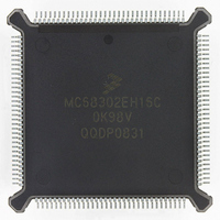
MC68302EH16C Freescale Semiconductor, MC68302EH16C Datasheet - Page 90

MC68302EH16C
Manufacturer Part Number
MC68302EH16C
Description
IC MPU MULTI-PROTOCOL 132-PQFP
Manufacturer
Freescale Semiconductor
Datasheets
1.MC68302AG20C.pdf
(4 pages)
2.MC68302AG20C.pdf
(2 pages)
3.MC68302AG20C.pdf
(13 pages)
4.MC68302EH16C.pdf
(481 pages)
Specifications of MC68302EH16C
Processor Type
M683xx 32-Bit
Speed
16MHz
Voltage
5V
Mounting Type
Surface Mount
Package / Case
132-MQFP, 132-PQFP
Controller Family/series
68K
Core Size
32 Bit
Ram Memory Size
1152Byte
Cpu Speed
16MHz
No. Of Timers
3
Embedded Interface Type
SCP, TDM
Digital Ic Case Style
PQFP
Rohs Compliant
Yes
Family Name
M68000
Device Core
ColdFire
Device Core Size
32b
Frequency (max)
16MHz
Instruction Set Architecture
RISC
Supply Voltage 1 (typ)
5V
Operating Temp Range
0C to 70C
Operating Temperature Classification
Commercial
Mounting
Surface Mount
Pin Count
132
Package Type
PQFP
Lead Free Status / RoHS Status
Lead free / RoHS Compliant
Features
-
Lead Free Status / Rohs Status
RoHS Compliant part
Electrostatic Device
Available stocks
Company
Part Number
Manufacturer
Quantity
Price
Company:
Part Number:
MC68302EH16C
Manufacturer:
Freescale Semiconductor
Quantity:
135
Company:
Part Number:
MC68302EH16C
Manufacturer:
PANA
Quantity:
99
Company:
Part Number:
MC68302EH16C
Manufacturer:
Freescale Semiconductor
Quantity:
10 000
Part Number:
MC68302EH16C
Manufacturer:
FREESCALE
Quantity:
20 000
Company:
Part Number:
MC68302EH16CB1
Manufacturer:
Freescale Semiconductor
Quantity:
10 000
Company:
Part Number:
MC68302EH16CR2
Manufacturer:
Freescale Semiconductor
Quantity:
10 000
- MC68302AG20C PDF datasheet
- MC68302AG20C PDF datasheet #2
- MC68302AG20C PDF datasheet #3
- MC68302EH16C PDF datasheet #4
- Current page: 90 of 481
- Download datasheet (2Mb)
System Integration Block (SIB)
REF—Output Reference Event
Bits 7–2—Reserved for future use.
3.5.2.6 General Purpose Timer Example
This section gives two examples on how to program the general purpose timers.
3.5.2.6.1 Timer Example 1
Generate an interrupt every 10 mS using the 20 MHz system clock.
Fine adjustments can be made to the timer by varying the TRR up or down.
3.5.2.6.2 Timer Example 2
Generate a 100 Hz square wave using the 20 MHz system clock. As in Timer Example 1,
the period is 10 mS, so we can use the same Prescaler and Reference values. When OM
is set, the TOUT pin only toggles when the reference value is reached. Therefore the refer-
ence value must be divided by two in order to generate two edges every 100 mS.
3-40
The counter has reached the TRR value. The ORI bit in the TMR is used to enable the
interrupt request caused by this event.
1. Take the desired interrupt period and divide by the timer clock period to get an initial
2. To calculate the value for the clock divider, divide the count by 65536 (2
3. The divider must be rounded up to the next integer value. A clock divider of 4 then
4. Program the TRR to $C350 ( = 50000 decimal).
5. Program the TMR to $031B (prescaler = 3, ORI =1 to enable interrupt, FRR = 1 to re-
1. Program the Port B control register to change the port pin from a general purpose input
2. Program the TRR to $61A8 ( = 50000/2).
3. Program the TMR to $321B (prescaler = 3, OM =1 to toggle TOUT, FRR = 1 to restart
count value to calculate prescaler.
changes the input timer period to Tin*4. A new count is calculated based on the new
timer period, and this value will be written to the TRR. The prescaler in the TMR is
equal to the clock divider minus 1 (or 4-1 = 3).
start counter after reference is reached, ICLK = 01 to use the master clock, and RST
= 1 to enabled the timer).
pin to TOUT.
Tout
------------ -
-------------------------------------
Tin Divider
Tin
Count
-----------------
65536
Tout
=
MC68302 USER’S MANUAL
------------------- -
------------------- -
20 MHz
10 ms
1
=
Divider
=
=
----------------------- -
50 ns 4
10 ms
Count
=
3.05176
=
=
200 000
50 000
,
,
16
).
MOTOROLA
Related parts for MC68302EH16C
Image
Part Number
Description
Manufacturer
Datasheet
Request
R
Part Number:
Description:
Manufacturer:
Freescale Semiconductor, Inc
Datasheet:

Part Number:
Description:
MC68302 Configuring the Chip Selects on the MC68302
Manufacturer:
Motorola / Freescale Semiconductor

Part Number:
Description:
MC68302 Design Concept - Expanding Interrupts on the MC68302
Manufacturer:
Motorola / Freescale Semiconductor

Part Number:
Description:
MC68302 MC68302 Adapting a WAN Controller to a LAN Environment
Manufacturer:
Motorola / Freescale Semiconductor

Part Number:
Description:
MC68302 EKB Applications - Power Measurements on the MC68302
Manufacturer:
Motorola / Freescale Semiconductor

Part Number:
Description:
MC68302 Interfacing the MC68020 to a Slave MC68302
Manufacturer:
Motorola / Freescale Semiconductor

Part Number:
Description:
MC68302 MC68302 Software Performance
Manufacturer:
Motorola / Freescale Semiconductor

Part Number:
Description:
MC68302 Evaluating EDX on the ADS302
Manufacturer:
Motorola / Freescale Semiconductor

Part Number:
Description:
MC68302 Design Advisory #1 - MC68SC302 Passive ISDN Protocol Engine
Manufacturer:
Motorola / Freescale Semiconductor

Part Number:
Description:
MC68302, MC68360, and MPC860 Characteristics and Design Notes for Crystal Feedback Oscillators
Manufacturer:
Motorola / Freescale Semiconductor
Part Number:
Description:
Mc68302 Integrated Multi-protocol Processor
Manufacturer:
Freescale Semiconductor, Inc
Datasheet:
Part Number:
Description:
Manufacturer:
Freescale Semiconductor, Inc
Datasheet:
Part Number:
Description:
Manufacturer:
Freescale Semiconductor, Inc
Datasheet:
Part Number:
Description:
Manufacturer:
Freescale Semiconductor, Inc
Datasheet:
Part Number:
Description:
Manufacturer:
Freescale Semiconductor, Inc
Datasheet:


