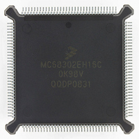
MC68302EH16C Freescale Semiconductor, MC68302EH16C Datasheet - Page 246

MC68302EH16C
Manufacturer Part Number
MC68302EH16C
Description
IC MPU MULTI-PROTOCOL 132-PQFP
Manufacturer
Freescale Semiconductor
Datasheets
1.MC68302AG20C.pdf
(4 pages)
2.MC68302AG20C.pdf
(2 pages)
3.MC68302AG20C.pdf
(13 pages)
4.MC68302EH16C.pdf
(481 pages)
Specifications of MC68302EH16C
Processor Type
M683xx 32-Bit
Speed
16MHz
Voltage
5V
Mounting Type
Surface Mount
Package / Case
132-MQFP, 132-PQFP
Controller Family/series
68K
Core Size
32 Bit
Ram Memory Size
1152Byte
Cpu Speed
16MHz
No. Of Timers
3
Embedded Interface Type
SCP, TDM
Digital Ic Case Style
PQFP
Rohs Compliant
Yes
Family Name
M68000
Device Core
ColdFire
Device Core Size
32b
Frequency (max)
16MHz
Instruction Set Architecture
RISC
Supply Voltage 1 (typ)
5V
Operating Temp Range
0C to 70C
Operating Temperature Classification
Commercial
Mounting
Surface Mount
Pin Count
132
Package Type
PQFP
Lead Free Status / RoHS Status
Lead free / RoHS Compliant
Features
-
Lead Free Status / Rohs Status
RoHS Compliant part
Electrostatic Device
Available stocks
Company
Part Number
Manufacturer
Quantity
Price
Company:
Part Number:
MC68302EH16C
Manufacturer:
Freescale Semiconductor
Quantity:
135
Company:
Part Number:
MC68302EH16C
Manufacturer:
PANA
Quantity:
99
Company:
Part Number:
MC68302EH16C
Manufacturer:
Freescale Semiconductor
Quantity:
10 000
Part Number:
MC68302EH16C
Manufacturer:
FREESCALE
Quantity:
20 000
Company:
Part Number:
MC68302EH16CB1
Manufacturer:
Freescale Semiconductor
Quantity:
10 000
Company:
Part Number:
MC68302EH16CR2
Manufacturer:
Freescale Semiconductor
Quantity:
10 000
- MC68302AG20C PDF datasheet
- MC68302AG20C PDF datasheet #2
- MC68302AG20C PDF datasheet #3
- MC68302EH16C PDF datasheet #4
- Current page: 246 of 481
- Download datasheet (2Mb)
Communications Processor (CP)
If in-line synchronization is used with the transparent controller, then the DSR (see 4.5.4
SCC Data Synchronization Register (DSR)) must be initialized with the SYN1–SYN2 syn-
chronization characters. See 4.5.16.5 Transparent Synchronization for details.
4.5.16.4 Transparent Commands
The following commands are issued to the command register.
STOP TRANSMIT Command
RESTART TRANSMIT Command
ENTER HUNT MODE Command
4.5.16.5 Transparent Synchronization
Once the SCC is enabled for transparent operation in the SCM, the transmit and receive
buffer descriptors are made ready for the SCC, and the transmit FIFO has been preloaded
by the SDMA channel (signaled by the RTS pin in NMSI and PCM modes), one additional
process must occur before data can be transmitted and received. This process is called
4-126
After a hardware or software reset and the enabling of the channel using the SCC mode
register, the channel is in the transmit enable mode and starts polling the first BD in the
table approximately every 16 transmit clocks.
The STOP TRANSMIT command aborts transmission. If this command is received by the
transparent controller during a buffer transmission, transmission of that buffer is aborted
after the FIFO contents (up to four words) are transmitted. The TBD# is not advanced.
Ones are continuously transmitted until transmission is re-enabled by issuing the RE-
START TRANSMIT command.
The STOP TRANSMIT command must be issued before the SCC mode register is used
to disable the transmitter if the transmitter is to be re-enabled at a later time.
The RESTART TRANSMIT command is used to begin or resume transmission from the
current Tx BD number (TBD#) in the channel's Tx BD table. When this command is re-
ceived by the channel, it will start polling the ready bit in this BD. This command is expect-
ed by the transparent controller after a STOP TRANSMIT command, after a STOP
TRANSMIT command and the disabling of the channel in its mode register, or after a
transmitter error (underrun or CTS lost occurs).
If the transmitter is being re-enabled, the RESTART TRANSMIT command must be used
and should be followed by the enabling of the transmitter in the SCC mode register.
After a hardware or software reset and the enabling of the channel in the SCC mode reg-
ister, the channel is in the receive enable mode and will use the first BD in the table.
The ENTER HUNT MODE command is used to force the transparent controller to abort
reception of the current block, generate an RX interrupt (if enabled) as the buffer is closed,
and enter the hunt mode. In the hunt mode, the transparent controller waits for a synchro-
nization to occur on the SCC (see 4.5.16.5 Transparent Synchronization). After receiving
the ENTER HUNT MODE command, the current receive buffer is closed. Reception con-
tinues using the next BD.
If an enabled receiver has been disabled (by clearing ENR in the SCC mode register), the
ENTER HUNT MODE command must be given to the channel before setting ENR again.
MC68302 USER’S MANUAL
MOTOROLA
Related parts for MC68302EH16C
Image
Part Number
Description
Manufacturer
Datasheet
Request
R
Part Number:
Description:
Manufacturer:
Freescale Semiconductor, Inc
Datasheet:

Part Number:
Description:
MC68302 Configuring the Chip Selects on the MC68302
Manufacturer:
Motorola / Freescale Semiconductor

Part Number:
Description:
MC68302 Design Concept - Expanding Interrupts on the MC68302
Manufacturer:
Motorola / Freescale Semiconductor

Part Number:
Description:
MC68302 MC68302 Adapting a WAN Controller to a LAN Environment
Manufacturer:
Motorola / Freescale Semiconductor

Part Number:
Description:
MC68302 EKB Applications - Power Measurements on the MC68302
Manufacturer:
Motorola / Freescale Semiconductor

Part Number:
Description:
MC68302 Interfacing the MC68020 to a Slave MC68302
Manufacturer:
Motorola / Freescale Semiconductor

Part Number:
Description:
MC68302 MC68302 Software Performance
Manufacturer:
Motorola / Freescale Semiconductor

Part Number:
Description:
MC68302 Evaluating EDX on the ADS302
Manufacturer:
Motorola / Freescale Semiconductor

Part Number:
Description:
MC68302 Design Advisory #1 - MC68SC302 Passive ISDN Protocol Engine
Manufacturer:
Motorola / Freescale Semiconductor

Part Number:
Description:
MC68302, MC68360, and MPC860 Characteristics and Design Notes for Crystal Feedback Oscillators
Manufacturer:
Motorola / Freescale Semiconductor
Part Number:
Description:
Mc68302 Integrated Multi-protocol Processor
Manufacturer:
Freescale Semiconductor, Inc
Datasheet:
Part Number:
Description:
Manufacturer:
Freescale Semiconductor, Inc
Datasheet:
Part Number:
Description:
Manufacturer:
Freescale Semiconductor, Inc
Datasheet:
Part Number:
Description:
Manufacturer:
Freescale Semiconductor, Inc
Datasheet:
Part Number:
Description:
Manufacturer:
Freescale Semiconductor, Inc
Datasheet:


