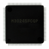
M30245FCGP#U1 Renesas Electronics America, M30245FCGP#U1 Datasheet - Page 65

M30245FCGP#U1
Manufacturer Part Number
M30245FCGP#U1
Description
IC M16C/24 MCU FLSH 128K 100LQFP
Manufacturer
Renesas Electronics America
Series
M16C™ M16C/20r
Datasheet
1.M30245FCGPU1.pdf
(268 pages)
Specifications of M30245FCGP#U1
Core Processor
M16C/60
Core Size
16-Bit
Speed
16MHz
Connectivity
I²C, SPI, SSI, UART/USART, USB
Peripherals
DMA, PWM, WDT
Number Of I /o
82
Program Memory Size
128KB (128K x 8)
Program Memory Type
FLASH
Ram Size
10K x 8
Voltage - Supply (vcc/vdd)
3 V ~ 3.6 V
Data Converters
A/D 8x10b
Oscillator Type
Internal
Operating Temperature
-20°C ~ 85°C
Package / Case
100-LQFP
Package
100LQFP
Family Name
R8C
Maximum Speed
16 MHz
Operating Supply Voltage
3.3 V
Data Bus Width
16 Bit
Number Of Programmable I/os
82
Interface Type
USB/UART/I2C/SPI
On-chip Adc
8-chx10-bit
Number Of Timers
5
Lead Free Status / RoHS Status
Lead free / RoHS Compliant
Eeprom Size
-
Available stocks
Company
Part Number
Manufacturer
Quantity
Price
- Current page: 65 of 268
- Download datasheet (3Mb)
M30245 Group
Figure 1.37. Block diagram of Key-input interrupt
Figure 1.38. Key-input mode register
Rev.2.00
REJ03B0005-0200
Enable/Disable
The key-input interrupts can be enabled and disabled in pairs using the Key-input mode register (03F9
input interrupt register (0041
enable flag (I flag). The input signal edge that triggers the Key-input interrupt can be selected by setting the P10 Key-
input edge select bits (bits 0 and 1 at 03F9
interrupt pins to input.
Oct 16, 2006
P10
P10
P10
P10
P10
Pull-up
transistor
7
6
5
4
0
/KI
/KI
/KI
/KI
/KI
7
6
5
4
0
Pull-up
transistor
Pull-up
transistor
Pull-up
transistor
transistor
Key-input mode register
Pull-up
b7
b6
page 63 of 264
KIE3
KIE2
KIE0
b5
Port P10
Port P10
Port P10
Port P10
Port P10
b4
b3
16
). The key-input interrupt is affected by the interrupt priority level (IPL) and the interrupt
7
b2
6
5
0
4
direction register
direction register
direction register
direction register
direction register
b1
Port P10
Port P10
b0
0
7
-P10
direction register
Bit Symbol
Nothing is assigned. Write "0" when writing to these bits.
The value is "0" if read.
KIS0
KIS1
KIE0
KIE1
KIE2
KIE3
7
Symbol
KUPM
16
pull-up select bit
KIS0, KIS1
). Also, make sure to set the port direction for the enabled Key-input
Edge detect
Edge detect
Edge detect
Edge detect
Edge detect
P10 Key-input edge select 0
P10 Key-input edge select 1
P10
P10
P10
P10
0
2
4
6
and P10
and P10
and P10
and P10
Bit Name
1
3
5
7
Key-input enable bit
Key-input enable bit
Key-input enable bit
Key-input enable bit
Address
0126
16
Key input interrupt control register
b1 b0
0 0 : Falling edge
0 1 : Rising edge
1 0 : Two edges
1 1 : Reserved
0 : Disabled
1 : Enabled
0 : Disabled
1 : Enabled
0 : Disabled
1 : Enabled
0 : Disabled
1 : Enabled
Interrupt control circuit
When reset
Function
00
16
O O
_ _
R W
O O
O O
O O
O O
O O
(address 0041
Key input interrupt request
16
Interrupts
)
16
) and Key-
Related parts for M30245FCGP#U1
Image
Part Number
Description
Manufacturer
Datasheet
Request
R

Part Number:
Description:
KIT STARTER FOR M16C/29
Manufacturer:
Renesas Electronics America
Datasheet:

Part Number:
Description:
KIT STARTER FOR R8C/2D
Manufacturer:
Renesas Electronics America
Datasheet:

Part Number:
Description:
R0K33062P STARTER KIT
Manufacturer:
Renesas Electronics America
Datasheet:

Part Number:
Description:
KIT STARTER FOR R8C/23 E8A
Manufacturer:
Renesas Electronics America
Datasheet:

Part Number:
Description:
KIT STARTER FOR R8C/25
Manufacturer:
Renesas Electronics America
Datasheet:

Part Number:
Description:
KIT STARTER H8S2456 SHARPE DSPLY
Manufacturer:
Renesas Electronics America
Datasheet:

Part Number:
Description:
KIT STARTER FOR R8C38C
Manufacturer:
Renesas Electronics America
Datasheet:

Part Number:
Description:
KIT STARTER FOR R8C35C
Manufacturer:
Renesas Electronics America
Datasheet:

Part Number:
Description:
KIT STARTER FOR R8CL3AC+LCD APPS
Manufacturer:
Renesas Electronics America
Datasheet:

Part Number:
Description:
KIT STARTER FOR RX610
Manufacturer:
Renesas Electronics America
Datasheet:

Part Number:
Description:
KIT STARTER FOR R32C/118
Manufacturer:
Renesas Electronics America
Datasheet:

Part Number:
Description:
KIT DEV RSK-R8C/26-29
Manufacturer:
Renesas Electronics America
Datasheet:

Part Number:
Description:
KIT STARTER FOR SH7124
Manufacturer:
Renesas Electronics America
Datasheet:

Part Number:
Description:
KIT STARTER FOR H8SX/1622
Manufacturer:
Renesas Electronics America
Datasheet:


